Appendix C UTILITY STANDARDS
ARTICLE A
Sanitary Sewer
DIVISION I
GENERAL SANITARY SEWER REQUIREMENTS
§ 1. General requirements.
§ 2. Drawings.
§ 3. As-built/record drawings.
§ 4. Qualifications of material and equipment.
§ 5. Product.
§ 6. Sewer construction requirements.
DIVISION II
SANITARY SEWAGE SERVICE CONNECTIONS SPECIFICATIONS
§ 1. Part 1 — General.
§ 2. Part 2 — Products.
§ 3. Part 3 — Execution.
DIVISION III
SANITARY SEWAGE SYSTEM SPECIFICATIONS
§ 1. Part 1 — General.
§ 2. Part 2 — Products.
§ 3. Part 3 — Execution.
DIVISION IV
LOW PRESSURE SEWER GRINDER PUMP STATIONS SPECIFICATIONS
§ 1. Part 1 — General.
§ 2. Part 2 — Products.
§ 3. Part 3 — Execution.
DIVISION V
SANITARY SEWER REQUIREMENTS DETAILS
ARTICLE B
Water Regulations
DIVISION I
GENERAL WATER SYSTEM REQUIREMENTS
§ 1. Application.
§ 2. Drawings.
§ 3. As-built/record drawings.
DIVISION II
SERVICE BACKFLOW PREVENTION/ CROSS CONNECTIONS
§ 1. Cross connections strictly prohibited.
§ 2. Requirements for backflow prevention.
DIVISION III
WATER SYSTEM SPECIFICATIONS
§ 1. Part 1 — General.
§ 2. Part 2 — Products.
§ 3. Part 3 — Execution.
DIVISION IV
RULES AND REGULATIONS
§ 1. Definitions.
§ 2. Applications for service.
§ 3. Service connections.
§ 4. Metered service.
§ 5. Payment for service.
§ 6. Termination of service.
§ 7. Fire service.
§ 8. Cross-connection control program.
§ 9. General rules and regulations.
DIVISION V
WATER REQUIREMENTS DETAILS
ARTICLE C
Storm Drainage
DIVISION I
STORM DRAINAGE SYSTEM SPECIFICATIONS
§ 1. Part 1 — General.
§ 2. Part 2 — Products.
§ 3. Part 3 — Execution.
DIVISION II
STORM DRAINAGE REQUIREMENTS DETAILS
ARTICLE D
Roadway Regulations
DIVISION I
BITUMINOUS PAVING SPECIFICATIONS
§ 1. Part 1 — General.
§ 2. Part 2 — Products.
§ 3. Part 3 — Execution.
DIVISION II
CEMENT CONCRETE WALKS SPECIFICATIONS
§ 1. Part 1 — General.
§ 2. Part 2 — Products.
§ 3. Part 3 — Execution.
DIVISION III
GRAVEL ROAD MIX SPECIFICATIONS
§ 1. Part 1 — General.
§ 2. Part 2 — Products.
§ 3. Part 3 — Execution.
DIVISION IV
EROSION AND SEDIMENT CONTROL SPECIFICATIONS
§ 1. Part 1 — General.
§ 2. Part 2 — Products.
§ 3. Part 3 — Execution.
DIVISION V
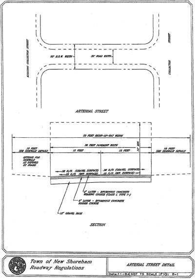
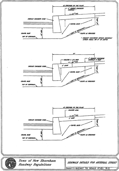
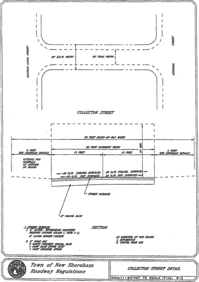
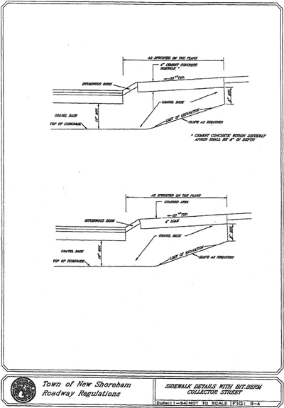
ROADWAY REQUIREMENTS DETAILS
Cross References Definitions and rules of construction generally, § 1-2.
Editor's Note: Printed herein are the Town of New Shoreham, Rhode Island, Utility Standards adopted by the New Shoreham Town Council, as amended on February 18, 2009. Subsequent amendments to the Standards are indicated by parenthetical history notes following amended provisions. The absence of a history note indicates that the provision remains unchanged from the original Standards. Obvious misspellings and punctuation errors have been corrected without notation.
ARTICLE A
Sanitary Sewer
DIVISION I
GENERAL SANITARY SEWER REQUIREMENTS
§ 1. General requirements.
1.1 The New Shoreham Board of Sewer Commissioners adopt the following priority among the existing enactments which affect sewer in the Town of New Shoreham.
• Public Acts establishing and amending the Sewer District: P.A. Chapter 146 (1972 as amended).
• Current Management Agreement between the Town of New Shoreham Director of Public Works, the New Shoreham Board of Sewer Commissioners and New Shoreham Board of Water Commissioners.
• Regulations adopted by the Sewer Commissioners subsequent to the adoption by the Rhode Island General Assembly of P.A. Chapter 146 (1972).
• Remaining provisions of enactments by the Town of New Shoreham, which are not inconsistent or superseded by the above legal enactments and documents.
1.2 Plans, specifications and design calculations for proposed sanitary sewage system(s), except for sanitary service connections, shall be submitted to the Sewer Superintendent for review. Design calculations shall conform to the Department of Environmental Management requirements.
1.3 Plans, specifications and calculations for sanitary sewage system extensions shall be prepared and stamped by an Engineer currently registered in the State of Rhode Island.
1.4 An Order of Approval shall be obtained from the Department of Environmental Management, when applicable.
1.5 Sewer Extensions.
• Sewer extensions will be allowed only if the receiving interceptors and pumping stations are capable of adequately processing the added hydraulic load. Documentation assessing the existing interceptor(s) and pumping station(s) shall be submitted to the Board of Sewer Commissioners. The documentation shall be stamped by a professional engineer registered in the State of Rhode Island.
• The proposed sewer extension must be consistent with the most recent Wastewater Management Facilities Plan adopted by the New Shoreham Board of Sewer Commissioners and the Rhode Island Department of Environmental Management.
§ 2. Drawings.
2.1 The applicant must furnish drawings showing the location of the premises together with the location of all underground piping, proposed connection points, applicable details, at the time of making the application.
2.2 Drawings shall be submitted on a maximum size of 24 inches by 36 inches prints. Two sets shall be submitted at the initial submission for indication of comments during the review stage. If a project is to be implemented in stages or phases, a master plan showing the entire site development, including all future expansion areas, shall be submitted for review during the first submission.
2.3 Drawings shall not be at a scale less than one inch per 40 feet and no more than one inch per 20 feet.
2.4 All site plans shall contain contours at a minimum of two-foot intervals based on National Geodetic Vertical Datum (N.G.V.D.) and not with assumed elevations. Site plans shall include a locus map at a scale of not less than one inch equals 2,000 feet and a north arrow.
2.5 All drawings are to be signed and wet-stamped by a registered, professional engineer licensed in the State of Rhode Island under whose direction the design has been designed.
§ 3. As-built/record drawings.
3.1 Upon completion of the project, the developer/owner shall provide a preliminary as- built drawing documenting the record of actual construction. The preliminary as-built drawing shall be on 24 inches by 36 inches sheets (plan scale one inch = 40 feet) for review prior to acceptance of the new construction infrastructure.
3.2 The owner/developer shall provide a revised as-built drawing reflecting measurements from the building foundations and above grade permanent structures and/or visible accessible permanent features. The final as-built drawing(s) set shall accurately mark the location of each infrastructure component or appurtenance as constructed including, but not limited to:
• Measured horizontal and vertical locations of the above and below grade sewer main, sewer services and appurtenances referenced to permanent surface improvements, above grade permanent structures and/or permanent visible and accessible features of the installation.
• Information concurrent with the actual construction.
• Three point measured swing ties from permanent surface improvements, above grade permanent structures and/or visible and accessible features of the installation to identify all bends, services and end caps.
• Depth of main at maximum of fifty-foot intervals. Ties at every 100-foot interval, each recorded service and at each bend.
• Total overall footage.
• Detail of sewer service connection to the main.
3.3 Upon approval of the "blue line" submission, a 6-mil, double matte Mylar media and print of the final "as-built" record drawing(s) shall be submitted and will remain the property of the Sewer Commission upon its approval and acceptance.
3.4 Upon final approval, the contractor shall also provide the "as-built" in AutoCad, latest edition digital format acceptable to the Sewer Commission.
§ 4. Qualifications of material and equipment.
4.1 Specific manufacturers' names and catalog numbers are used herein to establish quality and design of a particular item.
4.2 Wherever in the Specifications any item of equipment or material is designated by reference to a particular brand, manufacturer, or trade name, it is understood that a reviewed equal product, acceptable to the New Shoreham Board of Sewer Commissioners (NSBSC), may be submitted by the Contractor.
4.3 If the Contractor proposes to use a material which, while suitable for the intended use, deviates in any way from the detailed requirements, he shall inform the NSBSC in writing of the nature of such deviations at the time the material is submitted for review, and shall request a review of the deviation from the requirements.
4.4 In requesting a review of deviations or substitutions, the Contractor shall provide evidence leading to a reasonable certainty that the proposed substitution or deviation shall provide a result at least equal in quality to that specified. If, in the opinion of the NSBSC, the evidence presented by the Contractor does not provide a sufficient basis for such reasonable certainty, the NSBSC will reject such substitution or deviation without further investigation, in which case it shall be the responsibility of the Contractor to provide another product which is satisfactory to the NSBSC.
§ 5. Product.
5.1 Sanitary Sewer Information Required.
• All vertical and horizontal alignment (profile and plan).
• Size, slopes, and materials to be used.
• Invert and rim elevations.
• Location and details of manholes.
• Other existing and proposed utilities should be shown in order to avoid conflicts during construction.
• Design sanitary flow calculations with Professional Engineer's stamp, except for sanitary service connections. Calculations shall conform to the Department of Environmental Management (DEM) requirements.
§ 6. Sewer construction requirements.
6.1 General Requirements. Sanitary sewer improvements shall conform to the requirements of the New Shoreham Board of Sewer Commissioners, Department of Environmental Management, and any other agencies having jurisdiction.
6.2 Sanitary Sewers.
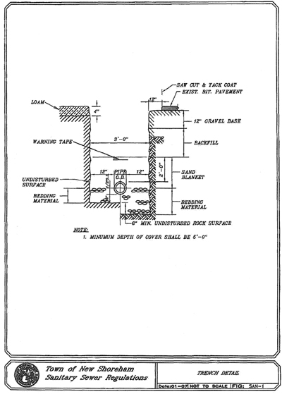
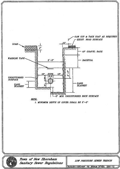
• sDepth. Sewers shall be designed deep enough to drain basement fixtures and to prevent freezing. The minimum depth of cover for street installation shall be six feet and for cross country installation it shall be four feet.
• Slope. The following minimum slopes may be used only if necessary because of grade restrictions.
| Sewer Size Inches | Minimum Slope Feet/Foot |
| 8 | 0.0040 |
| 10 | 0.0028 |
| 12 | 0.0022 |
| 14 | 0.0017 |
| 15 | 0.0015 |
| 16 | 0.0014 |
| 18 | 0.0012 |
| 21 | 0.0010 |
| 24 | 0.0008 |
| 27 | 0.0007 |
| 30 | 0.0006 |
| 36 | 0.0005 |
• Velocity. The minimum velocity for design purposes is two feet per second and the maximum velocity is 10 feet per second.
• Alignment. Sewers shall be laid with a straight alignment between manholes.
• Increasing Pipe Size. When a smaller sewer joints one of a larger one, the invert of the larger sewer should be lowered sufficiently to maintain the same hydraulic gradient.
• Materials. Sewers shall be constructed of materials described in Section II. Sewers crossing streams or any body of water shall be ductile iron encased in concrete.
• Manhole Locations. Manholes shall be installed at the end of each sewer line, at changes in grade, size, or alignment and at all intersections. The maximum spacing of manholes shall not exceed 300 feet.
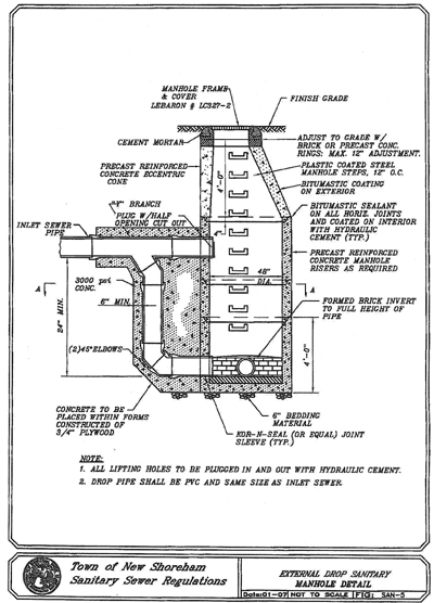
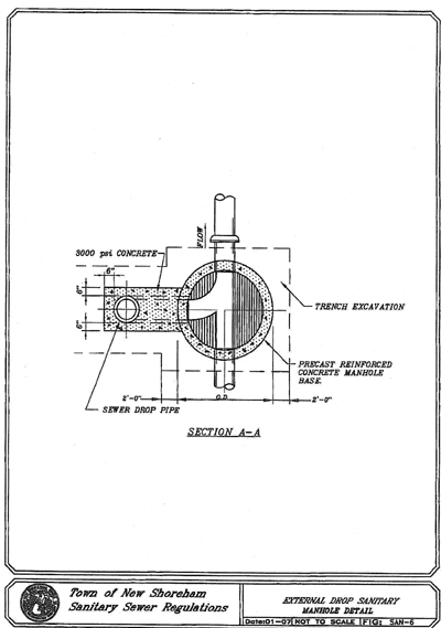
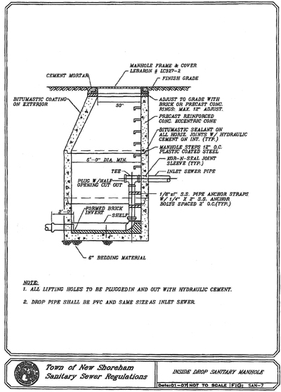
• Drop Manhole Type. A drop pipe should be provided for a sewer entering a manhole at an elevation of 24 inches or more above the manhole invert. The size of the drop pipe will be the same size as the sewer inlet pipe. Where the difference in elevation between the incoming sewer and the manhole invert is less than 24 inches, the invert shall be so constructed so that there is a smooth transition of flow in the manhole.
• Manhole Diameter. The minimum internal diameter of manhole shall be 48 inches.
• Flow Channel. A drop of at least 0.1 feet shall be provided between incoming and outgoing sewers on all manholes.
• Elevation. In all buildings in which any building drain is too low to permit gravity flow to the public sewer, sanitary sewage carried by such building drain shall be lifted by a grinder pump system as specified in Section A and discharged to the building sewer.
• Clean Outs. Clean-outs shall be installed at the property line, at every fitting over 22 1/2° and at seventy-five-foot intervals.
• Grease, Oil and Solids Interceptors. A user who is required to install a grease removal system may install either an outdoor passive in-ground grease interceptor or an automatic electrical/mechanical grease removal unit.
• In-ground grease removal systems shall have a minimum capacity of 500 gallons and shall have a capacity to provide at least a twenty-four-hour detention period for the process flow. The process flow shall be based on a minimum of 15 gallons per seat or chair per day or based upon actual water usage for existing facilities.
• The automatic electric/mechanical grease removal unit shall be the "Big Dripper" Automatic Grease Recovery System as manufactured by Thermaco, Inc., Asheboro, North Carolina, or equal. The unit shall be sized in accordance with the manufacturer's written recommendation. Influent to the unit with temperatures exceeding 150° will not be permitted.
• A separate suitable sampling location as approved by the Superintendent shall be provided for sampling of the discharge from the ground grease removable systems. The automatic electrical mechanical grease removal systems shall have a sampling valve installed on the discharge piping with a minimum clearance of eight inches to allow samples to be taken by representatives of the Board of Sewer Commissioners.
• Dishwasher wastewater shall not be discharged into the grease removal systems. The dishwasher wastewater shall bypass the grease removal system and discharge directly into the municipal sewer collection system except that the dishwasher wastewater from the pre-rinse station shall discharge to the grease removal system.
• Identification.
a) Underground-Type Line Markers for Non-Metallic Pipings. Manufacturer's standard permanent detection tape, bright colored, continuous-printed polyethylene tape with a metallic core for easy detection of non-metallic underground installations, intended for direct burial service; not less than six inches wide by 4 mils thick. Provide green detection tape with black printing reading "CAUTION SEWER LINE BURIED BELOW" as manufactured by Seton or equal.
b) Underground-Type Line Markers for Metallic Pipelines. Manufacturer's standard permanent, bright colored, continuous-printed polyethylene tape, intended for direct-burial service; not less than six inches wide by 4 mils thick. Provide green tape with black printing reading "CAUTION SEWER LINE BURIED BELOW" as manufactured by Seton or equal.
c) Installation marker two feet above top of pipe.
• Backflow Preventer. All connections are to be equipped with a backflow preventer. Backflow preventers must conform to the New Shoreham Building Inspector's requirements and the Building Officials Code Administrators Basic National Plumbing Code, Article 10, Section P-1003.0.
DIVISION II
SANITARY SEWAGE SERVICE CONNECTIONS SPECIFICATIONS
§ 1. Part 1 — General.
1.1 Description of Work.
A. The work consists of furnishing and installing service connections from the property line to building or from the main line to the building including, but not limited to, installation of appropriate fittings at the main sewer line, fittings at property line, construction of chimneys if required, construction of clean-outs, excavation, bedding, sand cushion, backfilling, recording location, and all other related and appurtenant work, complete in place in accordance with details and specifications, and as directed by New Shoreham Sewer Department (NSSD).
1.2 Special Requirements.
A. Contractor shall obtain all required permits as set forth in the Town of New Shoreham Sewer Ordinance prior to undertaking construction of sanitary sewage service connection(s).
B. The Sewer Superintendent shall be notified 24 hours in advance to inspect the installation of the sanitary sewage service connection(s).
C. Connections to sanitary manholes are not allowed.
§ 2. Part 2 — Products.
2.1 Pipe.
A. Polyvinyl Chloride and Fittings. Polyvinyl chloride (PVC) sewer pipe and fittings shall be in accordance with the latest issue of ASTM Specification D3034, SDR- 35 and applicable documents. The PVC sewer pipe and fittings shall be composed of clean, virgin class 12454-B compounds conforming to ASTM D1784 and shall be bell and spigot with rubber ring joints. The bell shall consist of an integral wall section with a solid cross section rubber ring securely locked in place to prevent dislocation of the ring. Standard lengths shall be 20 feet and 12.5 feet, plus or minus one-inch. Minimum "pipe stiffness" at 5% deflection shall be 46 for all sizes when tested in accordance with ASTM Designation D2412, external loading properties of plastic pipe by parallel-plate loading. All fittings and accessories shall be manufactured and furnished by the pipe supplier and have bell and/or spigot configurations compatible with that of the pipe fittings and shall be of the same strength and quality as the pipe.
B. Polyvinyl Chloride Pressure Pipe and Fittings. Polyvinyl chloride (PVC) pressure pipe and fittings shall be in accordance with AWWA C900, etc. bell and spigot with rubber ring joints. The pipe and fittings shall be Class 150 (DR18) with bell and spigot.
2.2 Chimneys.
A. Precast Units. The concrete shall be 5000 psi conforming to ASTM C150. Air entraining shall conform to ASTM C233, and the reinforcing shall conform to ASTM A615. All brackets, bolts, and nuts shall be stainless steel, and between each precast section there shall be a neoprene gasket.
2.3 Flexible Couplings.
A. Flexible couplings shall be as manufactured by Fernco or equal. The flexible coupling shall conform to ASTM C443, C425, C564, and D1869. The coupling shall have stainless steel clamps. Donuts are not allowed to be used in lieu of flexible couplings.
2.4 Sewer Pipe Saddle.
A. Sewer pipe saddles shall be Sealtite Type "D" Tee Sewer Pipe Saddle or Type "E" Wye Sewer Pipe Saddles as manufactured by Geneco Products or equal.
B. Saddle shall be cast iron conforming to ASTM A-48, Class 35 and shall be coated with a black asphaltum type paint.
C. Saddle gaskets shall be one piece, rubber O-rings, maintaining a leak-proof connection, conforming to ASTM DT869.
D. Saddle shall be secured to the existing sewer main with type C304 stainless steel band with stainless steel bolts.
2.5 Gravel Base.
A. Gravel shall be free of foreign material such as loam, silt, clay and vegetable matter and meet the following requirements:
| Passing 1 1/4-inch sieve | 100% |
| Passing 1 1/4-inch sieve | 30% - 65% |
| Passing No. 40 | 5% - 50% |
| Passing No. 100 | 0% - 10% |
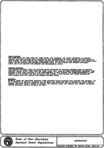
2.6 Bedding Material.
A. The bedding material shall be crushed stone consisting of durable crushed rock in durable crushed gravel stone, free from ice, snow, sand, clay, loam, or other deleterious material. The crushed stone shall conform to the requirements of 100% passing the one-inch screen, 90% - 100% passing the 3/4-inch screen, 10%
- 50% passing the 1/2-inch screen, 0% - 20% passing the 3/8-inch screen and 0%
- 5% passing the No. 4 sieve.
2.7 Sand Blanket.
A. The sand shall be free from ice, snow, roots, rubbish, and other deleterious or organic matter. The sand blanket shall conform to the requirements of 100% passing 1/2-inch screen, 85% - 100% passing the 3/8-inch screen, 60% - 85% passing the No. 4 sieve, 35% - 60% passing the No. 16 sieve, 10% - 35% passing the No. 50 sieve and 2% - 10% passing the No. 100 sieve.
2.8 Backfill.
A. Backfill shall be excavated materials free-draining clean granular soil suitable for backfill. Up to 20% of backfill material may be rock-like materials not to exceed
0.05 cubic feet in volume, nor more than six inches in length. The backfill shall not contain any debris, pavement, frozen material, organic matter, or peat.
§ 3. Part 3 — Execution.
3.1 Project Conditions.
A. Protection of Water Line.
1. Horizontal Separation. Sewers shall be laid at a minimum at least 10 feet, horizontally, from any existing or proposed water lines or service.
a. Should local conditions prevent a lateral separation of 10 feet, the sewer line shall be constructed of AWWA C900 polyvinyl chloride or Class 52 Ductile Iron pressure pipe.
2. Vertical Separation. Whenever sewers cross under water lines, or services, the sewer shall be laid at such an elevation that the top of the sewer is at least 18 inches below the bottom of the water lines. When the elevation of the sewer cannot be relocated to provide this separation the sewer line shall be constructed of AWWA C900 polyvinyl chloride or Class 52 Ductile Iron pressure pipe for a distance of 10 feet on each side of the water lines.
B. Private Wells. Sewers shall be laid at a minimum at least 50 feet, horizontally, from any existing or proposed private well. Should local conditions prevent a lateral separation of 50 feet, the sewer main shall be constructed of AWWA C900 polyvinyl chloride or Class 52 Ductile Iron pressure pipe from manhole to manhole reach including the service connection pipe.
3.2 Inspection.
A. The contractor shall notify the NSSD 24 hours in advance to make an inspection of the sanitary connection. The inspection(s) will be made prior to backfilling the trench. If more than one inspection is required to be made by the NSSD, the contractor will be required to reimburse the NSSD for the associated costs involved in the reinspection(s).
B. If during the inspection(s) it is found that the installation of the service connection is not in compliance with these specifications or details, the contractor shall immediately take corrective measures, and the service connection will be re- inspected at the contractor's expense.
3.2a Connections Made at Existing Sewer Main.
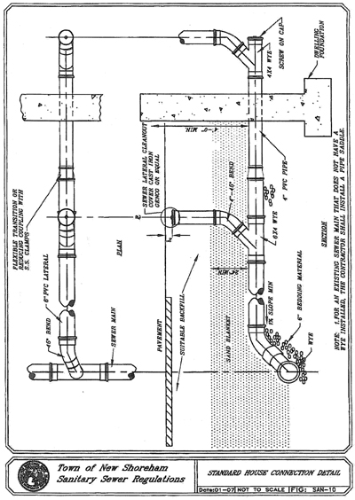
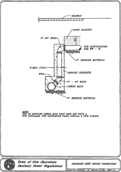
A. The contractor shall install a pipe saddle per manufacturer recommendations if a wye does not exist.
3.3 Connections Made at Property Line.
A. The contractor shall connect to the sewer service pipe located at the property line with a flexible coupling.
B. The contractor shall install a clean-out just upstream from the flexible coupling.
3.4 Clean-Outs.
A. Clean-outs shall be installed at the property line, at every fitting over 22 1/2° and at seventy-five-foot intervals up to 150 feet. Service connections which are longer than 150 feet shall have sanitary manholes installed at a locations(s) as directed by the NSSD.
3.5 Excavation and Backfill.
A. The width of the trench shall be held to a minimum consistent with the space required to permit satisfactory jointing of the pipe and tamping of the bedding and backfill material under and around the pipe. In general, the maximum trench width shall be the pipe diameter plus two feet or a minimum width of three feet, whichever is greater. If necessary, sheeting and/or shoring shall be used to prevent overcutting at the level of the top of the pipe and to maintain the trench sides. The trench bottom should be smooth, level and all large stones or rocks lying on or protruding from the trench bottom shall be removed. Over-excavation will be refilled in six-inch lifts with approved granular material and compacted to 95% maximum density.
B. Where unsuitable material is encountered at the trench bottom, the material shall be excavated to a stable bottom and refilled with compacted bedding material in six-inch lifts.
C. Backfill from the centerline of the pipe to a height of two feet above the pipe shall be sand blanket material placed evenly the full width of the trench and compacted in twelve-inch layers. The remainder of the trench shall be backfilled evenly with suitable (excavated or borrow) backfill material and compacted in twelve-inch layers. Cushion and backfill material shall be compacted to 95% maximum density by tamping and compacting in layers (one-foot maximum) to achieve the required compaction.
3.6 Installation of Pipe.
A. Each pipe length shall be inspected for cracks, defects in coating or lining, and any other evidences of unsuitability. Before lowering in place, the pipe shall be struck with a suitable tool to verify its soundness.
B. Pipe shall be laid in the dry and at no time shall water in the trench be permitted to flow into the sewer.
C. The pipe shall then be laid on the trench bedding as shown on the standard trench detail, and the spigot pushed home. Jointing shall be in accordance with the manufacturer's instructions and appropriate ASTM standards, and the contractor shall have on hand for each pipe-laying crew, the necessary tools, gauges, pipe cutters, etc., necessary to install the pipe in a workmanlike manner. Pipe laying shall proceed upgrade with spigot ends pointing in the direction of flow.
D. Blocking under the pipe will not be permitted except where a concrete cradle is proposed, in which case precast concrete blocks shall be used.
E. After the pipe has been set to grade, additional bedding material shall be placed in six-inch layers up to the spring line of the pipe. Tamping bars shall be carefully employed to assure compaction of the bedding under the lower quadrants of the pipe for the full width of trench excavation.
F. If inspection of the pipe is satisfactory, the contractor may then backfill the remainder of the trench in accordance to the specifications and details.
G. If a trench box is being used and the trench box is below the spring line of the pipe, the trench box shall be lifted vertically, and the stone bedding shall be thoroughly compacted to the trench wall. The trench box shall not be pulled horizontally along the trench.
H. At any time that work is not in progress, the end of the pipe shall be suitability closed to prevent the entry of animals, earth, etc.
I. Unsatisfactory work shall be dug up and re-installed to the satisfactory of the NSSD.
3.7 Recording Location.
A. The contractor shall submit to the NSSD, after completion of the service connection(s), installation of a sketch showing the location of the service connection utilizing distances from permanent structures. The depth at the sewer main property line and at the dwelling unit shall be recorded.
DIVISION III
SANITARY SEWAGE SYSTEM SPECIFICATIONS
§ 1. Part 1 — General.
1.1 Description of Work.
A. The work consists of furnishing and installing a sanitary sewerage system(s) including precast concrete manholes with accessories, pipe, pipe fittings and accessories, connections to other piping and structures, testing of manholes and piping, jointing, and jointing materials, by-pass sewage handling, excavation and backfill, bedding material, sand blanket, and all other related and appurtenant work, complete in place in accordance with the requirements set forth, and/or as directed.
1.2 Special Requirements.
A. All approvals and permits as set forth in the Town of New Shoreham Sewer Ordinance or New Shoreham Sewer Regulations must be obtained prior to constructions of sanitary sewage system.
B. The New Shoreham Sewer Department shall be notified 24 hours in advance to inspect construction, witness testing of pipelines and manholes and making connections to existing sanitary manholes.
1.3 Quality Assurance.
A. Manufacturer's Qualifications: Firms regularly engaged in manufacture of sanitary sewerage system's products of types, materials, and sizes required, whose products have been in satisfactory use in similar service for not less than five years.
1.4 Submittals.
A. General. All submittals shall be submitted to the Sewer Superintendent, New Shoreham Wastewater Treatment Facility, Spring Street, New Shoreham, Rhode Island.
B. Contract Drawings. Submit three sets of drawings of proposed sanitary sewage system for review.
C. Record Drawings. At completion of project, submit record drawings of installed sanitary sewerage piping showing a minimum of three ties from permanent installations such as poles, hydrants, etc., for manholes and service connections at main, property line, dwelling units and distances.
§ 2. Part 2 — Products.
2.1 Pipe.
A. Polyvinyl Chloride Pipe (six inches - 15 inches) and Fittings. Polyvinyl chloride (PVC) sewer pipe and fitting shall be in accordance with the latest issue of ASTM D3034, SDR35 and applicable documents. The PVC sewer pipe and fittings shall be composed of clean, virgin class 12364-C compounds conforming to ASTM D1784 and shall be bell and spigot with rubber ring joints. The bell shall consist of an integral wall section with a solid cross section rubber ring securely locked in place to prevent dislocation of the ring. Standard lengths shall be 20 feet and 12.5 feet, plus or minus one inch. Minimum "pipe stiffness" at 5% deflection shall be 46 for all sizes when tested in accordance with ASTM Designation D2412, external loading properties of plastic pipe by parallel-plat loading. All fittings and accessories shall be manufactured and furnished by the pipe supplier and have bell and/or spigot configurations compatible with that of the pipe fittings and shall be of the same strength and quality as the pipe.
B. Polyvinyl Chloride Pipe (greater than 15 inches) and Fittings. Polyvinyl chloride (PVC) sewer pipe and fittings shall be in accordance with the latest issue of ASTM F679. The PVC sewer and fittings shall be composed of clean, virgin, Class 12454C or 13364C compounds and shall be bell and spigot with rubber ring joints. The bell shall consist of integral wall section with a solid cross section rubber ring. Standard lengths shall be 13 feet plus or minus one inch. Minimum "pipe stiffness" at 7 1/2% deflection shall be 46 for all sizes when tested in accordance with ASTM Designation D2412. All fittings and accessories shall be as manufactured and furnished by the pipe supplier and have bell and/or spigot configurations compatible with that of the pipe fittings and shall be of the same strength and quality as the pipe.
C. Polyvinyl Chloride Pressure Pipe (six inches - 12 inches) and Fittings. Polyvinyl Chloride (PVC) pressure pipe and fittings shall be in accordance with AWWA C900 and shall be bell and spigot with rubber ring joints. The pipe shall be manufactured from PVC cell Class 12454-13 in accordance with ASTM D1784. The pipe and fittings shall be Class 150 (DR18) with bell and spigot.
1. Restrained Joint Pipe Fittings. In lieu of thrust blocks, mechanical joint restraints may be used. Calculations shall be submitted to the Sewer Superintendent as to the pipe lengths that will require the restraints.
a. Retainers for PVC pipe bells shall be cast from 60-42-10 ductile iron, as manufactured by EBAA Iron, or equal. These devices shall have a sufficient number of ductile tie bolts to restrain working and test pressures as stated by the manufacturer. Each ductile clamp shall have serrations on the I.D. sufficient to hold working and test pressures. These devices shall be used to restrain pipe joints adjacent to the restrained fittings. The 1500 and 6500 are used in place of concrete thrust blocks, steel clamps and tie rods.
b. When it is required to restrain PVC push-on joints adjacent to restrained fittings, a harness restraint device shall be used. This harness restraint shall be split to enable installation of the restraint after the spigot has been installed into the bell. The restraint shall consist of three major parts: the first part being a split ring that fits behind the bell; the second part being a split restraint ring that installs on the spigot; the third part being a number of tie bars to connect parts one and two to facilitate joint restraint. All of these components shall be cast of ductile iron conforming to ASTM A536-80. The restraint ring shall consist of a plurality of individually activated gripping surfaces to hold the spigot and maximize restrain capability. The harness restraint shall have a working pressure of at least 100 psi with a minimum safety factor of 2:1 and shall be EBAA Iron, Inc., MEGALUGR series 1100HV, or equal.
D. Ductile Iron Pipe and Fittings. Ductile iron pipe shall be furnished in accordance with ANSI Designation A21.51. The ductile iron pipe shall be thickness Class 52. Pipes shall have normal laying lengths of at least 18 feet. In addition, each length of pipe shall be cement lined and receive a factory applied interior and exterior coating of Kopper's Bitumastic Super Service Black or an approved coating of equal specifications in accordance with ANSI Designation A21.4. Ductile iron pipe shall be push-on type of joint which employs rubber gasket. Joints shall be in accordance with the latest ANSI standard for "Rubber Gasket joints for Ductile Iron Pressure Pipe and Fittings", Designation A21.11. Fittings shall be in accordance with ANSI 23.53 with mechanical joints. The fittings shall be coated inside and outside with a bituminous asphalt paint.
1. Restrained Joint Pipe and Fitting. In lieu of thrust blocks, mechanical joint restraints may be used. Calculations shall be submitted to the Sewer Superintendent as to the pipe lengths that will require the restraints. Mechanical joint restraints shall be incorporated in the design of the follower gland and shall include a restraining mechanism which, when actuated, imparts multiple wedging action against the pipe, increasing its resistance as the pressure increases.
a. Flexibility of the joint shall be maintained after burial. Glands shall be manufactured of ductile iron conforming to ASTM A 536. Restraining devices shall be of ductile iron heat treated to a minimum hardness of 370 BHN. Dimensions of the gland shall be such that it can be used with the standardized mechanical joint bell and tee-head bolts conforming to ANSI/AWWA A21.11 and ANSI/AWWA C153/ A21.53 of latest revision. Twist-off nuts shall be used to ensure proper actuating of the restraining devices. The mechanical joint restraint device shall have a working pressure of at least 250 psi with a minimum safety factor of 2:1 and shall be EBAA Iron, Inc. MEGALUGR or equal.
E. Flexible Couplings. Flexible couplings where used shall be as manufactured by Fernco Co. or equal.
F. Mechanical Couplings. Mechanical couplings shall be ductile iron style 38 as manufactured by Dresser, or equal, coated with a corrosion resistant coating applied by the factory.
G. Insulation of Underground Piping.
1. Insulation. Foam glass insulation, ASTM C552, "Specifications for Cellular Glass Thermal Insulation" shall be a minimum of three inches in thickness as manufactured by Pittsburgh Corning Corporation or equal.
2. Jacketing. The jacketing shall be Pittwrap Jacketing as manufactured by Pittsburgh Corning Corporation or equal.
3. Asphalt Coating. Pittcote 300 finish by Pittsburgh Corning Corp. or equal.
4. Reinforcing Fabric. PC Fabric 79 by Pittsburgh Corning Corp. or equal.
5. Strapping Tape. Glass fiber reinforced, one inch wide, Scotch Brand No. 880 by 3M or equal.
6. Bore Coating. Hydrocal B-11 by U.S. Gypsum or equal.
H. Thrust Blocks. Concrete for trust blocks shall be 3000 psi concrete.
2.2 Chimneys.
A. Precast Units. The concrete shall be 5000 psi conforming to ASTM C150. Air entraining shall conform to ASTM C233, and the reinforcing shall conform to ASTM A615. All brackets, bolts, and nuts shall be stainless steel, and between each precast section there shall be a neoprene gasket.
2.3 Manholes.
A. Poured-in-Place Manholes. Concrete for the bases or a complete manhole shall be 3000 psi. The bases or complete manholes shall be designed to withstand H20 loading without failure. Reinforcing steel shall be new deformed steel bars conforming to ASTM 615. Grade of steel shall be ASTM Grade 40 minimum. The exterior of the manhole shall be damp proofed with an asphaltic compound as manufactured by Hydrocide.
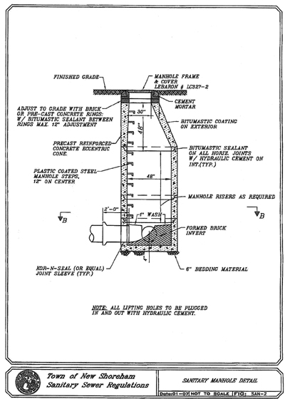
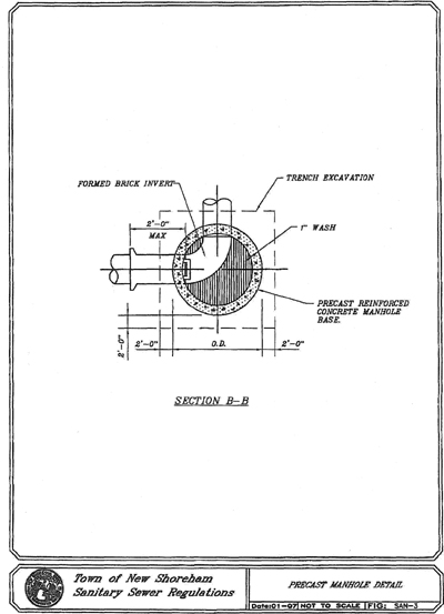
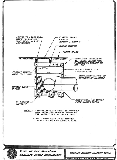
B. Precast Concrete Manholes. Manhole barrels, cone sections, bases, and entrance slabs shall consist of precast reinforced concrete manufactured in accordance with ASTM Standard Specifications for "Reinforced Concrete Manhole Risers and Tops", Designation C478 latest revision. The horizontal joints between sections shall be sealed using a flexible butyl resin sealant and shall conform to Federal Specifications SS-S-210A and AASHTO M-198B. The exterior of the manhole shall be damp proofed with an asphaltic compound as manufactured by Hydrocide.
C. Drop Manholes. Drop piping shall be the same size as sewer inlet. The concrete encasement for the drop piping shall be 3000 psi. Forms shall be used for the concrete encasement. The manhole shall be as specified for either cast-in-place or precast concrete manholes.
D. Pipe Connectors. Resilient complying with ASTM C923. For pipes up to 24 inches, the pipe connectors shall be Kor-N-Seal and for pipe over 24 inches, the pipe connector shall be A-Lok or equal.
E. Manhole Steps. Manhole steps shall be of safety type and shall be cast into the units during process of manufacture. Steps shall be steel reinforced copolymer polypropylene plastic step conforming to ASTM C478 or aluminum forgings alloy 6016, Temper T-16 and those parts which are embedded in the concrete shall be thoroughly cleaned and given a heavy coating of zinc chromate or other approved paint. In addition, steps shall conform to OSHA regulations.
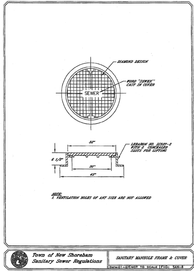
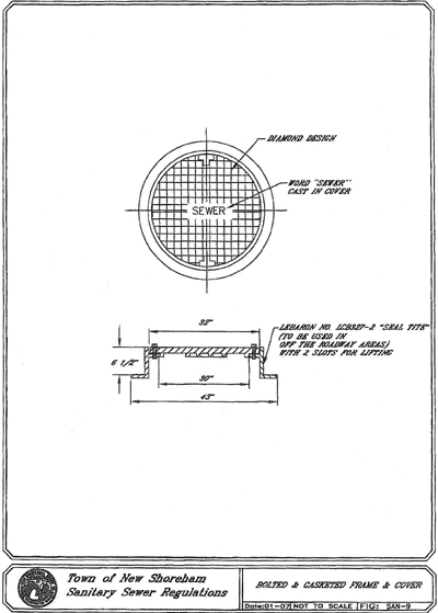
F. Frame and Covers. Manhole frames and covers shall be of tough gray cast iron, true to pattern and free from flaws. The bearing surfaces of the covers and frames shall be machined so as to give continuous contact throughout their circumference. The design on the cover top shall be the diamond with "sewer" lettering cast into the top surface.
G. Brick Masonry and Mortar Cement. Brick shall be Grade SM, ASTM C32 or Grade SM, AASHTO M91. All brick shall be common hard-rubber clay brick and shall be uniform and regular in shape and size. Mortar cement for masonry shall conform to ASTM Designation C-144. The mortar shall be composed of one part masonry cement to 2 1/2 parts sand with water not to exceed 4.1 gallons per 70 pound bag of masonry cement. If using Portland cement, lime putty may be added in such amounts that the hydrated lime does not exceed 15% by weight of cement.
2.4 Gravel Base.
A. Gravel shall be free of foreign material such as loam, silt, clay and vegetable matter and meet the following requirements:
Passing 1 1/4-inch sieve 100%
Passing 1/4-inch sieve 30% - 65%
Passing No. 40 5% - 50%
Passing No. 100 0% - 10%
2.5 Bedding Material.
A. The bedding material shall be crushed stone consisting of durable crushed rock or durable crushed gravel stone, free from ice, snow, sand, clay, loam or other deleterious material. The crushed stone shall conform to the requirements of 100% passing the 3/4 inch screen, 10% - 50% passing the 1/2 inch screen, 0% - 20% passing the 3/8 inch screen and 0% - 5% passing the number four sieve.
2.6 Sand Blanket.
A. The sand shall be free from ice, snow, roots, sod, rubbish, and other deleterious or organic matter. The sand blanket shall conform to the requirements of 100% passing the one-half-inch screen, 85% - 100% passing the 3/8 inch screen, 60% - 85% passing the number #4 sieve, 35% - 60% passing the number #16 sieve, 10% - 35% passing the number 50 sieve and 2% - 10% passing the number 100 sieve.
2.7 Backfill.
A. Backfill shall be excavated material free-draining clean granular soil suitable for backfill. Up to 20% of backfill material may be rock-like materials not to exceed
0.05 cubic feet in volume, nor more than six inches in length. The backfill shall not contain any debris, pavement, frozen material, organic matter or peat.
§ 3. Part 3 — Execution.
3.1 Project Conditions.
A. Protection of Water Line.
1. Horizontal Separation. Sewers shall be laid at a minimum at least 10 feet, horizontally, from any existing or proposed water main or service. Should local conditions prevent a lateral separation of 10 feet, the sewer line shall be constructed of Class 150 (DR18) polyvinyl chloride pressure pipe.
2. Vertical Separation. Whenever sewers cross under water mains, or services, the sewer shall be laid at such an elevation that the top of the sewer is at least 18 inches below the bottom of the water main. When the elevation of the sewer cannot be relocated to provide this separation, the sewer line shall be constructed of Class 150 (DR18) polyvinyl chloride pressure pipe for a distance of 10 feet on each side of the water main.
B. Private Wells. Sewers shall be laid at a minimum at least 50 feet, horizontally, from any existing or proposed private well. Should local conditions prevent a lateral separation of 50 feet, the sewer line shall be constructed of Class 150 DR18 polyvinyl chloride pressure pipe from manhole to manhole reach including the service connection pipe.
3.2 Inspection.
A. The Superintendent of the New Shoreham Sewer Department (NSSD) shall be notified prior to installation of a sanitary sewer system so that inspections can be made throughout the project.
B. The testing of sewer lines and manholes shall be conducted in the presence of the representatives of NSSD. The NSSD shall be notified 24 hours in advance of any testing.
C. Connections made to existing manholes for lateral sewers shall be inspected by the NSSD prior to backfill.
D. Connections to manholes for service connections are not allowed.
E. If during inspections it is found that the sewage system is not in compliance with the specifications or details, the deficiencies shall be corrected immediately to the satisfaction of the NSSD. The NSSD will not allow any further construction of the sewage system until such time the deficiencies are corrected.
3.3 Product Handling.
A. Each product shall be handled into its position in the trench in such a manner and by such means as the manufacturer recommends as satisfactory, and these operations will be restricted to those considered safe for the workmen and such as to cause no injury to the product or any property.
B. The contractor will be required to furnish slings, straps, and/or other devices to provide satisfactory support of the pipe when it is lifted. Transportation from delivery areas to the trench shall be restricted to operations which can cause no injury to the product. The products shall not be dropped from trucks or into the trench.
C. The contractor shall have on the job site with each crew, all the proper tools to handle the products being installed. The use of hammer and chisel or any other method which results in rough edges, chips and damages, shall be prohibited.
3.4 Excavation and Backfill for Pipes.
A. The width of the trench shall be held to a minimum consistent with the space required to permit satisfactory jointing of the pipe and tampering of the bedding and backfill material under and around the pipe. In general, the maximum trench width shall be the pipe diameter plus two feet or a minimum width of three feet, whichever is greater. If necessary, sheeting and/or shoring shall be used to prevent overcutting at the level of the top of the pipe and to maintain the trench sides. The trench bottom should be smooth, level and all large stones or rocks lying on or protruding from the trench bottom shall be removed.
Over-excavation shall be refilled in six inch lifts with approved granular material and compacted to 95% maximum density.
B. Where unsuitable material is encountered at the trench bottom, the material shall be excavated to a stable bottom and refilled with compacted bedding material in six inch lifts.
C. Backfill from the centerline of the pipe to the height two feet above the pipe shall be sand blanket material placed evenly the full width of the trench and compacted. The remainder of the trench shall be backfill material and compacted in twelve-inch layers. Cushion and backfill material shall be compacted to 95% maximum density by tamping and compacting in layers (one foot maximum) to achieve the required compaction.
3.5 Installation of Pipe.
A. Each pipe length shall be inspected for cracks, defects in coating or lining, and any other evidences of unsuitability. Before lowering in place, the pipe shall be struck with a suitable tool to verify its soundness.
B. Pipe shall be laid in the dry and at no time shall water in the trench be permitted to flow into the sewer.
C. The pipe shall then be laid on the trench bedding as shown in the trench detail, and the spigot pushed home. Jointing shall be in accordance with the manufacturer's instructions and appropriate ASTM standards, and the contractor shall have on hand for each pipe-laying crew, the necessary tools, gauges, pipe cutters, etc. necessary to install the pipe in a workmanlike manner. Pipe laying shall proceed upgrade with spigot ends pointing in the direction of flow.
D. Blocking under the pipe will not be permitted except where a concrete cradle is proposed, in which case precast concrete blocks shall be used.
E. After the pipe has been set to grade, additional bedding material shall be placed in six-inch layers up to the spring line of the pipe. Tamping bars shall be carefully employed to assure compaction of the bedding under the lower quadrants of the pipe for the full width of trench excavation.
F. If a trench box is being used and the trench box is below the spring line of the pipe, the trench box shall be lifted vertically and the stone bedding shall be thoroughly compacted to the trench wall. The trench box shall not be pulled horizontally along the trench.
G. At any time that work is not in progress, the end of the pipe shall be suitability closed to prevent the entry of animals, earth, etc.
H. Unsatisfactory work shall be dug up and re-installed to the satisfaction of the NSSD.
I. House service installations shall be as shown on the "Standard House Connection Detail". House services shall not be connected directly to manholes unless otherwise approved by the NSSD. The opening of the house service, wye branch or chimney shall be suitably plugged with a watertight cap or plug. Before backfilling, the contractor shall make the necessary measurements to locate the opening with a minimum of three ties later and the information shall be given to the NSSD. In addition, an approved ferrous rod or pipe shall be placed over the plugged opening, extending to within two inches of the final ground surface and metallic detection tape shall be installed a minimum of 24 inches above the pipe.
3.6 Installation of Manholes.
A. Bases for all sanitary sewer manholes shall be placed on a minimum of six inches of compacted bedding material. The excavation shall be properly dewatered and maintained dry while placing bedding material and setting the bases. Manholes shall be backfilled evenly and in layers, maximum one foot thick, with suitable backfill material and compacted to achieve 95% maximum density.
B. Sheeting and/or bracing shall be used when required.
C. Manhole barrel and cone sections shall be set so as to be vertical and in true alignment.
D. Where required for future connections, openings shall be cast in the manholes at the proper location and shall be sealed with plugs.
E. Drop manholes shall be built in accordance with the details.
F. The inverts of all manholes shall be constructed of brick and formed in accordance with the details.
G. Bricks shall be laid in a workmanlike manner, true to line and the joints shall be carefully struck and pointed on the inside. Bricks shall be thoroughly wet when laid and each brick shall be laid in mortar so as to form full bed, end and side joints in one operation. The outside of the brickwork shall be neatly plastered with one-half-inch layer of cement mortar as the work progresses. The brickwork shall be satisfactorily bonded to the concrete and cast iron frame. No brick masonry shall be laid in water, or any water allowed to rise on the brickwork until the masonry has set for at least 24 hours.
H. All lift holes shall be filled with non-shrinking mortar such as Quick-Plug prior to backfilling.
3.7 Connections to Existing Manholes.
A. Connections to existing manholes of lateral sewers shall be made so as not to damage the structure and shall be watertight with zero leakage. The crown of the new pipe shall be at the same elevation as the main of the largest existing pipe. The openings shall be cored and Kore-N-Tee boot shall be installed. The inverts shall be modified as directed to accommodate flow from the new pipe.
3.8 Placement of Thrust Blocks.
A. Thrust blocks shall be of sufficient size to withhold the test pressure, and they shall be paired against undisturbed earth. The concrete shall be kept clear of pipe joints.
3.9 Restrained Joints.
A. The mechanical joint restraints shall be installed in accordance with the manufacturer's written instructions.
3.10 By-Pass Sewage Handling.
A. As the construction of the sewer progresses and it becomes necessary to interrupt live sewage flow in any existing sanitary sewer, house lateral, manhole or portion thereof, the Contractor shall be required to divert such flows around the area of interruption.
B. The existing sewage flow rate shall be continually maintained at all times and no loss of sewer service up or downstream of the interruption shall occur. The contractor shall utilize quality materials and equipment in good repair in meeting the requirements of this special provision and all damages resulting from interruptions in the functioning of the by-pass sewage handling system shall be borne totally by the contractor. The contractor shall complete the adjacent construction in a timely fashion to minimize the duration of by-pass sewage handling required. Existing sewage flows shall be diverted and maintained until the new sewer construction is leakage tested and accepted for service by the NSSD.
3.11 Testing Gravity Sewers.
A. General. Testing of each section of sewer installed shall include the portions of service connections that are to be installed in the presence of the NSSD. The contractor shall test each manhole reach as soon as construction of such reach is complete. The contractor will be required to perform the pipe deflection test on each section of pipe installed, vacuum test of manholes and an infiltration test or low pressure test as applicable.
B. Pipe Deflection. Test each section of PVC sewer pipe for vertical ring deflection 60 days following installation. In the presence of the NSSD, maximum allowable ring deflection shall be 7 1/2% of inside diameter.
| 6 inches pipe | inside dia. 5.742 | 7.5% deflection 5.31 inches |
| 8 inches pipe | inside dia. 7.665 | 7.5% deflection 7.09 inches |
| 10 inches pipe | inside dia. 9.563 | 7.5% deflection 8.84 inches |
| 12 inches pipe | inside dia. 11.361 | 7.5% deflection 10.51 inches |
| 15 inches pipe | inside dia. 13.858 | 7.5% deflection 12.86 inches |
C. Infiltration Test. An infiltration test requires groundwater levels to be a minimum of two feet above the crown of the pipe of the high end of the section being tested. The contractor shall have on hand all plugs, pumps, weirs, water trucks, etc., necessary to conduct the tests.
1. Each manhole to manhole reach of pipeline shall be tested.
2. With all connecting pipes plugged (other than those included in test section) a V-notch weir shall be installed in the downstream end of pipe. The V- notch weir must be constructed accurately and installed to maintain a watertight seal between weir and pipe.
3. Time shall be allowed for water to build up behind weir until steady, uniform flow passes through V-notch.
4. Readings shall then be taken under direction of the NSSD and recorded.
5. Should the work fail the infiltration test, corrective action shall be taken by the contractor, in a manner approved by the NSSD. The sewer pipe shall be internally inspected with a camera to identify and locate the infiltration source(s). The contractor shall excavate and make the necessary repair to the satisfaction of the NSSD. The repair(s) shall be air tested with zero pressure drop after two minutes.
6. Leakage shall not exceed 10 gallons per inch diameter, per day, per mile of pipe. Should the pipe, as laid, fail to meet the requirements, the contractor shall perform the necessary work to meet these requirements.
D. Low Pressure Air Test.
1. After completing backfill of the pipeline, the contractor shall conduct a line acceptance test using low pressure air. The test shall be performed according to stated procedures and in the presence of the NSSD personnel. The line shall be flushed and cleaned prior to testing.
2. All pneumatic plugs shall be seal tested before used in the actual test installation. One length of pipe shall be laid on ground and sealed at both ends with the pneumatic plugs to be checked.
a. Air shall be introduced into the plugs to 25 psig. The plugs shall hold against this pressure without bracing and without movement of the plugs out of the pipe.
3. After a manhole to manhole reach of pipe has been backfilled and cleaned, and the pneumatic plugs are checked by the above procedure, the plugs shall be placed in the line at each manhole and inflated to 25 psig. Low pressure air shall be introduced into this sealed line until the internal air pressure reaches four psig greater than the average back pressure of any groundwater that may be over the pipe. At least two minutes shall be allowed for the air pressure to stabilize.
4. After the stabilization period (3.5 psig minimum pressure in the pipe), the air hose from the control panel to the air supply shall be disconnected. The time required in minutes for the pressure to decrease from 3.5 to 2.5 psig (greater than the average back pressure of any groundwater that may be over the pipe) shall not be less than the time shown for the given diameters in the following:
8 inches — 4 minutes
10 inches — 5 minutes
12 inches — 6 minutes
18 inches — 9 minutes
21 inches — 10 minutes
24 inches — 12 minutes
27 inches — 13 minutes
30 inches — 15 minutes
36 inches — 17 minutes
42 inches — 20 minutes
48 inches — 23 minutes
5. If the installation fails the air test, the contractor shall, at his expense, determine the source of leakage. The sewer pipe shall be internally inspected with a camera and each pipe joint shall be tested. The identified defect shall be repaired. The contractor will not be allowed to use sealants but will be required to excavate and make the necessary repair to the satisfaction of the NSSD and the pipeline shall be retested.
3.12 Testing of Pressure Lines.
A. Upon completion of installation of the force main, the line shall be tested for leaks. The contractor shall make all necessary arrangements for obtaining potable water, furnishing all pumps, piping, hose, installing corporation stops if necessary, etc.
B. Air shall be expelled by filling the main slowly and permitting air to escape at high points. Air bleeder shall be installed in location directed by the NSSD.
C. Pressure shall be applied and maintained at the low end of force main by means of pressure pump and by-pass on which a water meter and pressure gauge are mounted. Observations shall be made and metered water readings taken at varying pressures up to 150 lbs. per square inch not less than 125 lbs. Pressure shall be maintained for a period of one hour.
D. Any defective joints shall be immediately repaired, and any cracked or otherwise defective pipe shall be replaced by the contractor and the test repeated. As soon as satisfactory "test for strength" has been obtained, the by-pass with water meter and pressure gauge shall be left in service, and the section shall remain under a pressure of not less than 125 pounds per square inch until the leakage in the entire section does not exceed 10 gallons per day per mile of pipe per inch of nominal pipe diameter. In no case shall leakage tests be for less than four hours.
E. In the event the leakage exceeds the above stated maximum allowable, the contractor shall take such steps as are required and necessary or as are directed by the NSSD to reduce leakage to below the allowable maximum amount and shall replace any and all defective piping, and the test shall be repeated until the leakage requirements are complied with at no additional compensation to the contractor.
3.13 Testing of Manholes.
A. General. Tests shall be made and observed by the NSSD on each manhole.
B. Vacuum Test Before Backfilling. Install vacuum tester and inflate compression band to effect a seal between the vacuum base and the manhole, connect vacuum pump to the outlet part with the valve open, draw a vacuum of 10 inches of mercury (Hg), and close the valve. The manhole shall pass the test if the vacuum remains at 10 inches of Hg or drops to nine inches of Hg in a time greater than 60 seconds for a forty-eight-inch diameter manhole, time greater than 75 seconds for sixty-inch diameter manhole and time greater than 90 seconds for seventy- five-inch diameter manhole. If the manhole fails the initial test, the contractor shall make proper repairs or replace the manhole and retest at no additional compensation.
DIVISION IV
LOW PRESSURE SEWER GRINDER PUMP STATIONS SPECIFICATIONS
§ 1. Part 1 — General.
1.1 Description of Work.
A. The work consists of furnishing and installing a grinder pump system including excavation and backfill, bedding material, grinder pump, pump chamber with accessway, piping and valves, electrical work, factory and on-site testing, and all other incidentals as specified and as shown on the contract drawings.
B. All approvals and permits as set forth in the New Shoreham Sewer Ordinance and Regulations and the Department of Environmental Management requirements, when applicable, shall be obtained prior to the installation of the low pressure grinder pump station system.
1.2 Special Requirements.
A. Contractor shall obtain all required permits as set forth in the Town of New Shoreham Sewer Ordinance and the Regulations of the New Shoreham Board of Sewer Commissioners prior to undertaking construction of sanitary sewage service connection(s).
B. The Sewer Superintendent shall be notified 24 hours in advance to inspect the installation.
1.3 Submittals.
A. Contract Documents. Submit contract documents of proposed low pressure sewer grinder pump system including design calculations.
B. Operation and Maintenance Service. Submit an operation and maintenance service contract for each grinder pump unit.
C. Record Drawings. At completion of project, submit record drawings of installed system.
1.4 Qualifications of Material and Equipment.
A. Specific manufacturers' names and catalog numbers are used herein to establish quality and design of a particular item.
B. Wherever in the specifications any item of equipment or material is designated by reference to a particular brand, manufacturer, or trade name, it is understood that a reviewed equal product, acceptable to the New Shoreham Board of Sewer Commissioners (NSBSC), may be submitted by the Contractor.
C. If the Contractor proposes to use a material which, while suitable for the intended use, deviates in any way from the detailed requirements, he shall inform the NSBSC in writing of the nature of such deviations at the time the material is submitted for review, and shall request a review of the deviation from the requirements.
D. In requesting a review of deviations or substitutions, the Contractor shall provide evidence leading to a reasonable certainty that the proposed substitution or deviation shall provide a result at least equal in quality to that specified. If, in the opinion of the NSBSC, the evidence presented by the Contractor does not provide a sufficient basis for such reasonable certainty, the NSBSC will reject such substitution or deviation without further investigation, in which case it shall be the responsibility of the Contractor to provide another product which is satisfactory to the NSBSC.
§ 2. Part 2 — Products.
2.1 Grinder Pump Unit.
A. The grinder pump unit shall be Model GP212 or GP214 with redundant check valve and accessway as required and a Control Panel MOD 150-4 or MOD160-Y as manufactured by Environmental One Corporation. A high level indicator lamp assembly shall be provided requiring 120 Volts and a decorative wall plate marked "Grinder Pump Monitor".
2.2 Piping.
A. Low pressure pipe and fittings shall be polyvinylchloride pipe Class 200 (SDR
21) with push-on joints. Bell shall be gasketed joint conforming to ASTM D3139 with gaskets conforming to ASTM F477.
B. Schedule 80 PVC pipe and fittings shall be rigid, unplasticized, Type I, Grade I, polyvinylchloride conforming to ASTM D1784, NSF listed.
2.3 Electrical Equipment.
A. Manual transfer switch shall be a double throw non-fuse, 3-pole square "D" 30 amp enclosed in a NEMA3R enclosure.
B. The generator hook-up shall be a single outlet (2P-3 wire) twist lock with a weather-proof cover plate NEMA L6-30 or with a 12-2 with ground power supply cord connected to the transfer switch with a male plug.
C. All materials shall be U.L. listed, PVC conduits, conduit wall seals and conductors-copper and shall be acceptable to the local electrical inspector.
§ 3. Part 3 — Execution.
3.1 Installation of Grinder Pumping Unit.
A. Installation of grinder pumping unit shall be in accordance with the manufacturer's written instructions.
B. Installation of piping and valves shall be in accordance to sanitary sewage system or sanitary sewage service connections specifications.
3.2 Electrical.
A. Contractor shall obtain all required certificates of inspection of his work as required by state and local officials and deliver same to the New Shoreham Sewer Department (NSSD).
B. All materials furnished and all work installed shall comply with the national fire codes of the National Fire Protection Association, with the requirements of all town, state and governmental departments having jurisdiction, including applicable requirements of the U.S. Department of Labor's occupational safety and health standards.
C. Materials and workmanship shall be new and of current production and shall conform in all respects to applicable requirements of national electrical code, rules, and regulations governing installation of electrical work in the applicable requirements of the utility company and other state and local authorities having jurisdiction.
D. The high level indicator lamp assembly shall be installed in a standard device box in a visible location in the interior of dwelling.
3.3 Start-Up Service.
A. A factory-trained representative shall perform initial start-up of each unit and instruct dwelling owner in the operation and maintenance of the equipment, and test for satisfactory performances of each unit in the presence of the Sewer Superintendent.
3.4 Operation and Maintenance Service.
A. A two year operation and maintenance service contract for the pumping unit shall be obtained by the contractor or dwelling owner for each unit and submitted to the Sewer Superintendent prior to receiving a permit for installation.
DIVISION V
SANITARY SEWER REQUIREMENTS DETAILS


ARTICLE B
Water Regulations
DIVISION I
GENERAL WATER SYSTEM REQUIREMENTS
§ 1. Application.
1.1 The New Shoreham Board of Water Commissioners adopt the following priority among the existing enactments which affect water in the Town of New Shoreham:
• Public Acts establishing and amending the Water District; P.A. Chapter 18 (2000 as amended).
• Current Management Agreement between the Town of New Shoreham Director of Public Works, the New Shoreham Board of Sewer Commissioners and the New Shoreham Board of Water Commissioners.
• Regulations adopted by the Water District subsequent to the adoption by the Rhode Island General Assembly of P.A. Chapter 18 (2000).
• Remaining provisions of enactments by the Town of New Shoreham, which are not inconsistent or superseded by the above legal enactments and documents.
1.2 The proposer must complete the applicable service application forms, along with all supporting documents as required for the project contemplated, to obtain approval for:
• A service extension
• A main extension
• A request for service to a new project
• An upgrade or change in use or occupancy that affects the water service requirements of the existing property
1.3 Application for service must be made in writing on the prescribed form, and signed by the owner or duly authorized agent. The application must fully state the purpose for which the water will be used, together with the proper legal description of the property, official town or city street and property owner of the premises or property to be supplied. All accompanying design drawings, calculations and pertinent detailed project data must be attached to the application.
1.4 In all cases where fire services may be required, a letter of review detailing the needed fire flow demand requirements for the sprinkler system must accompany the application submission. The review letter shall be signed by the local fire chief or district authority.
1.5 The proposal package must be in full compliance with all the rules, regulations and utility standards, along with any pertinent state and local regulations or codes.
• Should the proposal package be found deficient in any manner during the initial review, a full re-submission shall be required.
• All documents, along with the revised "Request for Plan Review Application" form, must be contained in the revised submission. The revised submission shall include all pertinent information from previous submissions and 2 sets of the revised plans.
1.6 It is expressly understood that the developer and/or proposer is entirely responsible for providing a project proposal package and design that is in full compliance with the current rules, regulations and utility standards. The Water Board assumes no responsibility for project proposal packages or design that do not fully comply with current Water Board requirements.
1.7 The applicant must follow the Rules and Regulations made by the New Shoreham Water District, as amended from time to time (included as Exhibit A in Section B). The Rules and Regulations constitute a contract between the customer and Water District upon acceptance by the District of an application for water service. The customer is considered to have expressed its consent to be bound thereby and to take water only for the purposes stated in the application at the established rate.
§ 2. Drawings.
2.1 The applicant must furnish drawings showing the location of the premises to be supplied together with the location of all valves, pipes, hydrants, tanks, sprinkler heads, proposed connection points, applicable details, general notes, utility conflict corrections, and other appurtenances to be installed on the premises at the time of making the application.
2.2 The applicant also agrees to furnish the Water Board with drawings showing revisions to piping or appurtenances. The drawings shall become and remain the property of the Water Board.
2.3 Drawings shall be submitted on a maximum size of 24 inches by 36 inches prints. Two sets shall be submitted at the initial submission for indication of comments during the review stage. If a project is to be implemented in stages or phases, a master plan showing the entire site development, including all future expansion areas, shall be submitted for review during the first submission.
2.4 Drawings shall not be at a scale less than one inch per 40 feet and no more than one inch per 20 feet.
2.5 All site plans shall contain contours at a minimum of two foot intervals based on National Geodetic Vertical Datum (N.G.V.D.) and not with assumed elevations. Site plans shall include a locus map at a scale of not less than one inch equals 2,000 feet and a north arrow.
2.6 A thrust block or restrained joint pipe table shall be included on the plan reflecting the size(s) for all thrust blocks, length of all restrained pipe per fitting style and the accompanying fittings proposed.
2.7 All drawings are to be signed and wet-stamped by a registered, professional engineer licensed in the State of Rhode Island under whose direction the design has been prepared.
2.8 All applicable details shall be shown on the drawing sets.
§ 3. As-built/record drawings.
3.1 Upon completion of all water main infrastructure and appurtenance work, the developer/owner shall provide a preliminary as-built drawing documenting the record of actual construction. The preliminary as-built drawing shall be on 24 inches by 36 inches sheets (plan scale one inch equals 40 feet) for review prior to activation of the new construction infrastructure. Upon approval by the Water Board, water service may be activated to facilitate development of the site.
3.2 The owner/developer shall provide a revised as-built drawing reflecting measurements from the building foundations and above grade permanent structures and/or visible accessible permanent features to water appurtenances (such as bends, valve boxes, services, and so on). Valve boxes, curb boxes and telephone poles are not considered permanent features to retain measurements from. The final as-built drawing(s) set shall accurately mark the location of each infrastructure component or appurtenance as constructed including, but not limited to:
• Measured horizontal and vertical locations of the above and below grade water main, valves, fittings, services and appurtenances referenced to permanent surface improvements, above grade permanent structures and/or permanent visible and accessible features of the installation.
• Information concurrent with the actual construction.
• Distance from the main to curb box at each service.
• 3 point measured swing ties from permanent surface improvements, above grade permanent structures and/or visible and accessible features of the installation to identify all bends, services and end caps.
• Depth of main at maximum of fifty-foot intervals. Ties at every 100-foot interval, each recorded service and at each bend.
• Total overall footage.
• Detail of water main tap connection and all utility crossings.
• The completed water main and its proper orientation.
• Valve opening rotation (open left).
3.3 Upon approval of the "blue line" submission, a 6-mil, double matte Mylar media and print of the final "as-built" record drawing(s) shall be submitted and will remain the property of the Water Board upon its approval and acceptance.
3.4 Upon final approval, the contractor shall also provide the "as-built" in AutoCad and PDF, latest edition digital format acceptable to the Water Board.
3.5 Water service will not be activated until all requirements have been met to the satisfaction of the Water Board.
DIVISION II
SERVICE BACKFLOW PREVENTION/CROSS CONNECTIONS
§ 1. Cross connections strictly prohibited.
A. No person shall cause a physical connection to be made between the Water District water supply and any other water supply for any purpose, but not limited to commercial, domestic, sanitary, fire protection or boiler feed.
B. No plumbing fixtures, devices, or construction shall be installed which may provide a cross connection between the Water District supply and a drainage system, soil or waste pipe, so as to permit or make possible the backflow of sewage or waste into the supply system. Draw-off pipes for draining sprinkler systems shall not be connected into a drainage system or a submerged pit.
C. If the Water District water supply is delivered to a tank that is also supplied with water from any other source, the tank shall be open to atmospheric pressure and the Water District water supplied above the maximum level in the tank. The tank shall be equipped with an overflow pipe of ample size to ensure a fixed maximum water level. There shall be at least a six-inch air gap between the invert of the pipe supplying Water District water and the maximum level of water in the tank.
D. In the event that the Water District water supply is delivered to a tank in which there are chemicals, dyestuffs or other materials used in processing, the pipe supplying Water District water shall not be submerged. There shall be ample clearance between the invert of the Water District supply pipe and the top of the tank to prevent back- siphonage into the Water District supply.
§ 2. Requirements for backflow prevention.
A. All commercial and industrial users shall be equipped with reduced pressure zone backflow preventer of a testable type immediately downstream of the water meter. Prior to installation and service activation, the Water District shall determine style and type.
B. High and moderate hazards to the system are to be protected through the installation of a reduced pressure zone type of backflow device assembly. High and moderate hazard uses include, but not limited to the following: metal plating process, hospital, nursing home, clinic, hotel, mortuary, laboratory, film processing, car washing, chemical process or storage, food processing, restaurant, irrigation systems, hair salon, sewage treatment, chemical fire protection, or any commercial building with the ability for occupancy changes.
C. Low hazards are to be protected by the installation of a double or dual check valve backflow device assembly. Low hazard operations include, but not limited to single- family residential structures.
D. In all cases, backflow prevention shall be installed and be operational prior to connection to the Water District's system. Commercial connections shall be equipped with a reduced pressure zone style backflow preventer in order to isolate the public water system prior to service connection. Valves shall be located on both sides of the backflow preventer with drain or test plug on the valve located between the meter and backflow device.
E. It is required that applicant's professional engineer review all piping within any proposed development building or industrial facility and identify locations where isolation backflow preventers will be needed to protect the water supply from potential contamination.
F. All single family residential units must be equipped with residential double or dual check valve on the effluent side of the meter and non-removable vacuum breakers on all outside hose bibs prior to service connection and meter installation. Style shall be non-removable self- draining types.
G. All commercial or residential lawn sprinkler systems must be provided with an appropriate pressure backflow device assembly where the system connects to water supply. It shall be in a location that is always free draining and cannot be submerged.
H. All permanently connected fire sources and private hydrants shall be equipped with isolation type reduced pressure backflow preventers of a testable type (i.e., RPZ). Backflow prevention may be incorporated into the meter system piping. The device shall be placed in a location that is protected from damage by frost.
I. Installations that require additional backflow prevention are outlined in the Block Island Water Company's Utilities Standards and should be referred to for further information and requirements.
J. Installation of a backflow device assembly will prevent release of on site pressure to the utility water mains. It is mandatory a thermal expansion device be properly installed pursuant to all government plumbing codes to relive any excessive increase in on site pressure due to hot water heating systems or other activities systems.
K. Backflow prevention devices shall be installed above ground, heated and lighted. Where the building point-of-entry is located more than 200 feet from the curb stop, the backflow prevention device shall be installed in an accessible location in the building at the point of entry before the first tap, and any appliance or pumping unit.
Installation of backflow prevention devices in below ground pits shall be avoided whenever possible. If it is necessary that the backflow prevention device be mounted in a pit, it shall be lighted; power ventilated, heated and free draining under all conditions. Redundant pumping capable of contending with the full relief flows of the backflow and a monitoring alarm is also required for below grade applications.
L. The installer and/or owner of the facility must employ the OSHA Confined Space Entry Requirements and shall follow the OSHA Safety Rules and use required safety equipment available whenever anyone must enter the pit. In all cases, the backflow prevention device assembly site shall be easily accessible for testing and/or repair. Federal Occupational Safety and Health Administration (OSHA) rules, regulations and statutes are incorporated by reference and made a part herein.
DIVISION III
WATER SYSTEM SPECIFICATIONS
§ 1. Part 1 — General.
1.1 Description of Work.
A. The Contractor shall obtain all Town permits necessary to complete the installation of a water system. The work consists of furnishing and installing water pipe, pipe fittings and specials, valves, valve boxes, hydrants, water service connections, connections of existing and new piping, miscellaneous metal for strapping piping, underground line markers, accessories, miscellaneous and appurtenant work for providing construction as directed, complete in place tested, disinfected and accepted.
1.2 Special Requirements.
A. The Superintendent of the Block Island Water Company (BIWC) shall be notified 24 hours in advance to inspect construction, witness testing and take water samples.
1.3 Submittals.
A. Contract Drawings. Submit three sets of drawings of proposed water system or water service to the Water Superintendent for review.
B. Record Drawings. At completion of project, submit record drawings of installed water system or water service piping showing a minimum of three ties from permanent installations such as poles, hydrants, etc., for valves, bends and service connections at main, property line and dwelling unit and distances.
§ 2. Part 2 — Products.
2.1 Identification.
A. Underground-Type Line Markers for Non-Metallic Pipings. Manufacturer's standard permanent detection tape, bright colored, continuous-printed polyethylene tape with a metallic core for easy detection of non-metallic underground installations, intended for direct-burial service; not less than six inches wide by four mils thick. Provide blue detection tape with black printing reading "CAUTION WATER LINE BURIED BELOW" as manufactured by Seton or equal.
B. Underground-Type Line Markers for Metallic Pipelines. Manufacturer's standard permanent, bright colored, continuous-printed polyethylene tape, intended for direct-burial service; not less than six inches wide x four mils thick. Provide blue tape with black printing reading "CAUTION WATER LINE BURIED BELOW" as manufactured by Seton or equal.
2.2 Pipe and Pipe Fittings.
A. Ductile iron fittings shall conform to ANSI/AWWA C153/A21.53. Foreign fittings, gasket glands and accessories are strictly forbidden. All fittings shall have a bituminous outside coating in accordance with ANSI/AWWA C151/ A21.51 and ANSI/AWWA C153/A21.53 respectively. All fittings shall be cement-mortar lined and seal coated in accordance with ANSI/AWWA C104/ A21.14 except the lining thickness shall be twice that specified. Joints for fittings shall be mechanical joint conforming to ANSI/AWWA C111. All mechanical joint fittings shall be supplied with glands and accessories.
1. Type. Four-inch to twelve-inch Ductile Iron compact meeting ANSI/ AWWA C153/A21.53.
2. Pressure Class. Pipe fittings shall have a pressure rating of 350 for twelve- inch and smaller. Fittings shall, at a minimum, have the same pressure rating as the connecting pipe.
3. Gaskets. Rubber meeting ANSI/AWWA C111/A21.11. Nitrile (in contaminated soil).
4. Restrained Joint Pipe and Fittings. Mechanical joint restraints shall be incorporated in the design of the follower gland and shall include a restraining mechanism which, when actuated, imparts multiple wedging action against the pipe, increasing its resistance as the pressure increases. Flexibility of the joint shall be maintained after burial. Glands shall be manufactured of ductile iron conforming to ASTM A 536-80. Restraining devices shall be of ductile iron heat treated to a minimum hardness of 370 BHN. Dimensions of the gland shall be such that it can be used with the standardized mechanical joint bell and tee-head bolts conforming to ANSI/ AWWA A21.11 and ANSI/AWWA C153/A21.53 of latest revision. Twist- off nuts shall be used to insure proper actuating of the restraining devices. The mechanical joint restraint device shall have a working pressure of at least 250 psi with a minimum safety factor of 2:1 and shall be EBAA Iron, Inc. MEGALUG or equal.
B. Couplings shall be furnished with corrosion-proof vinyl coating on middle ring and followers.
C. Polyvinyl Chloride (P.V.C.) Piping. Piping shall be Class 150 conforming to AWWA C900 standard specification and the pipe shall have integral bell and spigot joints through 12 inches. The P.V.C. pipe shall be supplied in lengths not in excess of 20 feet. Each pipe shall have cast on it; nominal size, AWWA pressure class, dimension production record code and seal of testing agency that verified the suitability of the pipe material for potable water.
1. Fittings. The fittings shall be cast-iron or ductile iron compiling to the requirements stated under "Ductile-Iron Piping" with mechanical joint restraints.
2. Mechanical joint restraint shall be incorporated in the design of the follower gland. The restraint mechanism shall consist of a plurality of individually activated gripping surfaces to maximize restraint capability. Glands shall be manufactured of ductile iron conforming to ASTM A536-80. Dimensions of the gland shall be such that it can be used with the standardized mechanical joint bell and tee-head bolts conforming to ANSI/AWWAA21.11/C111 and ANSI/AWWA A21.53/C153 of latest revision. Twist-off nuts, sized same as tee-head bolts, shall be used to insure proper actuating of restraining devices. The mechanical joint restraint shall have a working pressure of at least 100 psi with a minimum safety factor of 2:1 and shall be EBAA Iron, Inc., MEGALUGR or equal. The length of upstream and downstream piping requiring mechanical joint restraint from a fitting shall be in accordance with the manufacturer's requirements.
3. When it is required to restrain PVC push-on joints adjacent to restrained fittings, a harness restraint device shall be used. This harness restraint shall be split to enable installation of the restraint after the spigot has been installed into the bell. The restraint shall consist of three major parts: the first part being a split ring that fits behind the bell; the second part being a split restraint ring that installs on the spigot; the third part being a number of tie bars to connect parts one and two to facilitate joint restraint. All of these components shall be cast of ductile iron conforming to ASTM A536-80. The restraint ring shall consist of a plurality of individually activated gripping surfaces to hold the spigot and maximize restraint capability. The harness restraint shall have a working pressure of at least 100 psi with a minimum safety factor of 2:1 and shall be EBAA Iron, Inc., MEGALUGR, Series 1100HV or equal.
2.3 Flexible Couplings.
A. Where flexible couplings are to be installed, they shall be Dresser, Skinner, Smith Blair or equal for Class 52 Ductile Iron Pipe. Coupling shall be furnished with corrosion-proof vinyl coating on middle ring and followers. Adapters shall conform to the manufacturers specifications.
2.4 Strap Rods.
A. For purpose of anchoring pipe or fittings shall be 3/4 inch round steel or wrought iron. Clamps shall be not less than two inches wide and 3/8 inch round. Clamps and rods are to be protected against corrosion by heavy coat of bituminous asphalt varnish after final assembly. Where pipe or fittings will be exposed under normal conditions, joints shall be sufficiently restrained so as to prevent blow off of pipe or fittings or movement of same during normal use.
2.5 Thrust Blocks.
A. Concrete for thrust blocks shall be 3000 psi.
2.6 Hydrants.
A. Fire hydrants. Fire hydrants shall be in accordance with the requirements of the latest "Standard Specification for Fire Hydrants for Ordinary Water Works Service" as adopted by the American Water Works Association, Specification AWWA C502-64, as manufactured by Mueller Centurion, size 4 1/2 inch. Hydrants shall meet the specific requirements and exceptions of the aforementioned specifications as follows:
1. Hydrants shall be so constructed that if accidentally broken off at top, i.e., above grade, the top section can readily be replaced without closing any valves outside the hydrant, and without excavation.
2. Hydrants shall be unsuitable to set in a trench four feet to six inches deep, that being the distance from the ground surface to the underside of the six inches pipe connecting with the hydrant. Hydrant extension pieces, barrel type shall be furnished for depths exceeding four feet to six inches as directed by the Superintendent.
3. Hydrant drain outlet shall be surrounded with not less than two cubic feet of washed stone or crushed gravel.
4. Hydrants shall open LEFT, hydrant head shall have arrow to indicate opening direction.
5. Hydrants furnished shall be complete, i.e., with no additional fittings or conveniences (other than replacement parts) to be purchased by the Town.
6. Contractor shall paint exposed portion of hydrants with a field coat of red paint and a finish coat of high grade oil paint in colors to be selected by the Town. Below ground, hydrants shall be coated with pitch tar varnish of same composition as AWWA specifications for tar coated pipe.
B. Hydrant Wrench. One hydrant wrench shall be provided to the Town. The wrench shall be pentagonal non-adjustable and specifically for use with hydrants.
2.7 Valves.
A. Resilient Seat Gate (four-inch to twelve-inch).
1. Type: Buried Service non-rising stem. Above grade service or pits OS&Y with hand wheel or non-rising stem with hand wheel.
2. Working Pressure: 250 psi
3. Opening: Left on system location.
4. Stem: 420 stainless steel or equal with minimum 60,000 psi yield strength.
5. Fasteners: Stainless steel, type 304 for all of the valves.
6. Coatings: Internal and exterior to be coated with fuse bonded holiday-free epoxy coating, minimum eight mils nominal thickness, meeting or exceeding AWWA C550.
7. Wedges: Fully rubber encapsulated cast iron, ductile iron or bronze gate meeting AWWA C509.
8. Opening Nut: two-inch square operating nut with hexagon stainless steel bolt fastener.
9. Stem Seal: Minimum two O-ring seals.
10. Connection: Mechanical joint.
B. Tapping Sleeves and Valves. Valves shall be full body and full port tapping type meeting the requirements for resilient seat gate valves. Sleeves shall be full port ductile iron or grade 18-8 type 304 stainless steel. Ductile iron sleeves shall be of the same manufacturer as of the valve and bituminous coated. All sleeves shall be manufactured to meet or exceed the design and operating characteristics of one of the following devices:
1. Type. Resilient seat gate valves designed specifically for tapping.
2. Seal. Stainless steel sleeves shall use grid pattern virgin rubber ASTM 2000, full 360° pipe coverage. Ductile iron sleeves shall use mechanical joint with rubber seals.
C. Valve Boxes. Valve boxes shall be two piece, buffalo type, adjustable of the sliding type, round body, heavy pattern, with at least 10 inches of overlap of top section over the other and with flanged top section. The castings shall be made of gray cast-iron, true to pattern and free from flaws. They shall be thoroughly coated with an asphaltum varnish, inside and out. The covers shall be 5 1/4-inch diameter solid ring seat with the word "WATER" cast in the top. At the completion of the work, valve boxes shall be set plumb and flush with the road surface.
D. The upper portion of the box shall be manufactured with a heavy flange having sufficient bearing area to prevent settlement. The lower section shall be configured to enclose the valve stuffing box with an inside diameter of at least 4 1/4-inch. The installed box shall be capable of vertical adjustment of a minimum of six-inch while maintaining an overlap of at least four-inch between sections.
E. Valve Key. The Contractor shall furnish one standard valve operating key to the Town.
2.8 Insulation of Underground Piping.
A. Foamglass Insulation. ASTM C552 "Spec. for Cellular Glass Thermal Insulation" shall be three inches thick as manufactured by Pittsburgh Corning Corporation.
B. Jacketing. The jacketing shall be Pittwrap Jacketing as manufactured by Pittsburgh Corning Corporation.
C. Asphalt Coating. Pittcote 300 finish by Pittsburgh Corning Corporation.
D. Reinforcing Fabric. PC Fabric 79 by Pittsburgh Coming Corp.
E. Strapping Tape. Glass fiber reinforced, one-inch wide, Scotch Brand No. 880 by 3M.
F. Bore Coating. Hydrocal B-11 by U.S. Gypsum.
2.9 Service Connections.
A. Service pipe sizes to two-inch shall be H.D.P.E. pipe. Color must be blue with a virgin clear natural center. Continuous identification markings over the entire length of the pipe with sealed ends and coiled in rolls from 100-ft. minimum.
1. H.D.P.E. shall conform to ASTM D1248 Type III, Grade P34, Class A, Category 5, color blue with virgin clear natural center, AWWA C901, 200 psi (CTS).
B. Corporation Stops. Corporation stops shall be lead-free brass full port ball and plug style with a thick wall cast brass body and stainless steel stem. The inlet connection shall be tapered AWWA (cc) and the outlet connection compression type. The corporation stop shall be equal to American Water Works Association standards as manufactured by Mueller, Cambridge, or Red Hed.
C. Curb Stops. Curb stops shall be lead-free full port ball style with a thick wall cast brass body with drain and stainless steel stem. The inlet and outlet shall be compression type. The stop shall have 90° rotation with casted arrow depicting direction of flow. The curb stop shall be equal to American Water Works Association Standards as manufactured by Mueller, Cambridge or Red Hed. The Contractor shall furnish to the Town, two socket wrenches suitable for operating curb stops. One end of wrench handle shall have a socket of proper size and shape to remove curb stop box cover nuts.
D. Curb Boxes. Curb boxes shall be of cast-iron of one of the standard makes, sliding, New England Style, inside cover, with upper § 2 1/2 inches or larger, and shall be coated with asphaltum varnish, inside and out. They shall have round covers with the word "WATER" cast thereon. Boxes shall be adjustable for a maximum bury of four feet-six inches. Cover shall be attached to box with locknuts or lock lugs.
E. Backflow Preventers. All devices must have been approved by the University of Southern California (FCCCHR, USC), American Water Works Association and American Society of Sanitary Engineers. Backflow device assemblies tested with manufacturer's isolation valves to meet FCCCHR, USC standards shall be installed with the manufacturer valves as an assembly. Bronze or brass components shall meet or exceed the lead leaching performance specifications of ANSI/NSF 61 Standard or be manufactured with lead-free "Environ Brass II" USN Alloy Number C89520, ASTM B584-98a.
1. Testable Double Check.
a. Type: Watts or equal.
b. Body: Cast iron, bronze or stainless steel (depending on size).
c. Coating: Iron components shall be epoxy coated AWWA C-500
d. Springs: Stainless steel.
e. Pressure: Maximum 150 psi - Minimum 10 psi.
2. Testable Reduced Pressure.
a. Type: Watts or equal.
b. Body: Cast iron, bronze or stainless steel (depending on size).
c. Coating: Iron components shall be epoxy coated AWWA C-500.
d. Springs: Stainless steel.
e. Pressure: Maximum 175 psi - Minimum 10 psi.
3. Household Dual Check.
a. Type: Watts or equal.
b. Body: Cast bronze.
c. Springs: Stainless steel.
d. Pressure: Maximum 150 psi - Minimum 10 psi.
F. Saddles. Service saddles and repair saddles shall be ductile iron or type 304 stainless steel, with stainless steel bolts, washers, nuts and bands. Ductile iron components shall be coated with fusion bonded epoxy minimum eight mils thickness meeting or exceeding AWWA C550 or nylon coated. Saddles shall be manufactured to meet or exceed the design and operating characteristics of the following:
1. Service.
a. Type: Ford or equal.
b. Body: Ductile iron or grade 18-8 type 304 stainless steel.
c. Coating: Ductile iron components shall be epoxy coated AWWA C500 or nylon coated.
d. Band: Grade 18-8 type 304 stainless steel double band.
e. Fasteners: 304 stainless steel stud, nut and washers.
f. Gasket: Virgin rubber ASTM 2000.
g. Outlet: Threaded outlet tapped to AWWA C800 for the appropriate service size.
2. Repair.
a. Type: Ford or equal.
b. Body: Ductile iron or grade 18-8 type 304 stainless steel.
c. Coating: Ductile iron components shall be epoxy coated AWWA C500 or nylon coated.
d. Band: Grade 18-8 type 304 stainless steel double band.
e. Fasteners: 304 stainless steel stud, nut and washers.
f. Gasket: Virgin rubber ASTM 2000.
g. Outlet: Threaded outlet tapped to AWWA C800 for the appropriate service size.
2.10 Gravel Base.
A. Gravel shall be free of foreign material such as loam, silt, clay and vegetable matter and meet the following requirements:
| Passing 1 1/4-inch sieve | 100% |
| Passing 1/4-inch sieve | 30% - 65% |
| Passing No. 40 | 5% - 50% |
| Passing No. 100 | 0% - 10% |
2.11 Bedding Material.
A. Pipe bedding shall be processed borrow gravel, granular in nature, the major portion of which may be sand or gravel. It shall be free from peat, vegetable or organic matter or any other debris and readily compactable. Recycled road sweepings and contaminated material are forbidden.
B. Selected backfill may be from excavated materials that shall be free draining, clean, granular soil suitable for backfill. It shall be free from peat, vegetable or organic matter or any other debris and shall be readily compactable to the requirements of BIWC, type 5 trench. Recycled road sweepings and contaminated material are forbidden. Up to 20% may be rock-like material, not to exceed three inches in length or diameter, and must be evenly distributed within the total volume of the fill.
2.12 Sand Blanket.
A. The sand shall be free from ice, snow, roots, sod, rubbish, and other deleterious or organic matter. The sand blanket shall conform to the requirement of 100% passing the 1/2-inch screen, 85 to 100% passing the 3/8-inch screen, 60 to 85% passing the No. 4 sieve, 35% - 60% passing the No. 16 sieve, 10 to 35% passing the No. 50 sieve and 2% to 10% passing the No. 100 sieve.
2.13 Backfill.
A. Backfill shall be excavated material free-draining clean granular soil suitable for backfill. Up to 20% of backfill material may be rock-like materials not to exceed
0.05 cubic feet in volume, not more than six-inches in length. The backfill shall not contain any debris, pavement, frozen material, organic matter, or peat.
§ 3. Part 3 — Execution.
3.1 Earthwork.
A. Cutting Pavement. Excavations made on pavement shall be made in a careful manner so as to cause the least amount of damage to the pavement. Pavement shall be saw cut prior to trench excavation. Pavement and/or cement concrete will be cut 12 inches either side of the maximum allowable trench width. Any damage to the cut line due to the excavations, backfilling or removal of temporary pavement shall be re-cut to neat lines. The width of pavement removed shall be kept as narrow as practicable. Existing pavement and base course disturbed or damaged shall be replaced by the Contractor to match existing pavement and base course. Excavated pavement shall not be mixed with other excavated material which is to be used as backfill, and shall be removed immediately from the site of the work.
B. Trench Excavation. Trenches shall be excavated to lines and grades shown on the drawings and shall include the removal of materials such as clay, pavements, sand, gravel, soft or disintegrated rock, which in the opinion of the Superintendent can be removed without blasting or drilling, and boulders less than one cubic yard in volume. Wherever rock is encountered in trench excavation, rock shall be removed by a method acceptable to the Superintendent to the lines and grades indicated on the plans, or to a minimum depth of six inches beneath the pipe barrel. Final decision as to suitability of excavated material for use as backfill or fill shall be made by the Superintendent. If in the judgment of the Superintendent the excavated material is unsuitable, the Contractor shall import bank run gravel to make up the deficiency.
C. Excavation Support System. The Contractor shall furnish, put in place, maintain and remove, as required and/or necessary for safe and proper construction in accordance with OSHA regulations, all excavation support systems which may be required to support the sides of the excavation, preventing damage to persons, adjacent property and structures.
D. Pumping and Dewatering. The Contractor shall furnish all pumps, equipment, power and attendance to maintain and operate such pumping and dewatering systems consisting of any means and devices, including spare units in case of breakdown, which accomplish the removal and prompt disposal of all water entering the excavation. The pumping manner, method or both shall be sufficient such that the natural state of the soil is not significantly disturbed and that groundwater is controlled at levels which will permit all work to be performed in dry conditions.
E. Excavation and Backfill for Pipes.
1. The width of the trench shall be held to a minimum consistent with the space required to permit satisfactory jointing of the pipe and tampering of the bedding and backfill material under and around the pipe. In general, the maximum trench width shall be the pipe diameter plus two feet or a minimum width of three feet, whichever is greater. If necessary, sheeting and/or shoring shall be used to prevent overcutting at the level of the top of the pipe and to maintain the trench sides. The trench bottom should be smooth, level and all large stones or rocks lying on or protruding from the trench bottom shall be removed.
Over-excavation shall be refilled in six lifts with approved granular material and compacted to 95% maximum density.
2. Where unsuitable material is encountered at the trench bottom, the material shall be excavated to a stable bottom and refilled with compacted bedding material in six-inch lifts.
3. Backfill from the centerline of the pipe to the height two feet above the pipe shall be sand blanket material placed evenly the full width of the trench and compacted. The remainder of the trench shall be backfill material and compacted in twelve-inch layers. Cushion and backfill material shall be compacted to 95% maximum density by tamping and compacting in layers (one-foot maximum) to achieve the required compaction.
3.2 Identification Markers.
A. Install identification marker two feet below grade above top of pipe or in accordance with requirements of state in which project is located.
3.3 Inspection.
A. All pipe, fittings, valves and hydrants shall be carefully inspected for defects immediately prior to placing in the trench.
3.4 Installation of Pipe.
A. Each pipe shall be handed into the trench carefully and in a workmanlike manner. The Contractor shall furnish all slings and straps to permit satisfactory support of all parts of pipe when it is being handled. The Contractor shall take all necessary precautions to prevent movement of pipe in the event of the trench flooding. Any length of pipe broken or damaged shall be replaced.
B. Ends of pipe shall be thoroughly cleaned before joint is made. The surface of the joint shall be painted with required lubricant applied in accordance with the manufacturer's direction. The lubricant shall be of type recommended by pipe manufacturer. Pipes shall be jointed in strict accordance with pipe manufacturer's directions and work shall be done by skilled workmen.
C. No pipe or fittings shall be laid in water or on a frozen trench bottom or when the trench conditions or the weather are unsuitable for such work. All joints shall be checked by feeler ring gauge to insure proper positioning of rubber gaskets.
3.5 Fittings.
A. Fittings of the proper type shall be furnished and installed wherever shown on the drawings and as required by the Block Island Water Company.
B. The fittings shall be supported on cement blocks to prevent settlement and resulting shear action to attached pipes. Cement blocks at fittings shall remain in place. At all plugged tees the plug shall be strapped to tee.
C. Bends and tees shall be installed in the mains where shown on the contract drawings. Vertical bends where shown on the drawings shall be anchored in both directions with pipe-clamps and tie-rods. All other fittings shall be equipped with proper sized thrust blocks poured against undisturbed earth. The Contractor shall provide the necessary tie rods and clamps. Tie rods and clamps shall be as manufactured by the Grinnel Company, Inc. or equal.
3.6 Restrained Joints.
A. Fittings and bends may be restrained through the use of mechanical joints with MEGALUG® or with thrust blocks. If mechanical joints with MEGALUG® are utilized, the required length upstream and downstream pipe shall be restrained based on the manufacturer's recommendation.
B. Thrust blocks shall be of sufficient size as shown in the details to prevent movement or the pipe shall in all cases be poured against undisturbed earth. Where thrust blocks are in contact with the pipe, concrete shall be kept clear of pipe joints.
C. Concrete thrust blocks shall be constructed at all underground cast-iron fittings that results in a change of direction of pipe line. Thrust blocks shall be of bearing size indicated on the drawings.
3.7 Installation of Valves.
A. Each valve shall be equipped with a gate box set vertically with top even with finished grade.
3.8 Method of Installing Services.
A. Services shall be installed by open cut method. Under no circumstances will tunneling under surfaced roadways be permitted.
3.9 Service Taps.
A. Taps for service connections shall be made with a standard tapping machine, using a sharp tap, the threads of which shall have the same taper as the taper of the threads on the corporation stop. Service taps shall be of the size directed by the Superintendent.
3.10 Couplings and Connections.
A. All couplings for service piping and connectors to corporation and curb stops shall be flared tube or compression type.
3.11 Hydrants.
A. Hydrants shall set straight and true on a firm base. Bury shall be four feet-six inches to centerline of inlet. Each hydrant shall be equipped with a thrust block, drain connection, and gravel drainage pocket all as shown on the contract drawings. The Contractor shall supply the necessary 3/4 inch threaded to copper fittings and 3/4 inch Type K soft copper tubing to install the hydrant drain connections.
3.12 Deflection.
A. Wherever curves are negotiated by deflecting successive lengths of pipe the deflection of each length of pipe shall not exceed 3°, or as recommended by manufacturer.
3.13 Insulation of Underground Piping.
A. Insulation and jacket shall be installed in accordance with written manufacturer's installation procedures. Prior to backfilling, roofing felt shall be placed over the Pittcote 300 coatings.
3.14 Field Quality Control.
A. Pressure Testing.
1. All services, water mains, bypass piping and appurtenances must be installed prior to commencement of any test. A pressure test shall be conducted on all completed water lines prior to acceptance. The proposer, at no cost to the BIWC, shall accomplish the pressure test. An authorized representative of the BIWC shall witness the test.
2. Each valve section of the main shall be filled slowly with water at a rate no greater than one foot of pipe section per second. All air shall be released via corporation stops, hydrants, and installed automatic air release fittings. All air must be removed and the full pipe shall sit idle for a period of 24 hours prior to commencement of the pressure test. Piping installations greater than 1,000 feet shall be accomplished in sections no greater than 1,000 feet.
3. The test pressure shall be brought up to at least 50% higher than the normal anticipated working pressure, or 150 psi, whichever is greater, and maintained for a continuous two-hour period. An authorized representative of the BIWC shall witness the test. Any loss of pressure indicates a leak, and no pipe installation will be accepted with any leakage.
4. Proper thrusting of all pipefitting, caps, hydrants and appurtenances shall be provided to resist the imposed test pressure.
B. Chlorination/Disinfection.
1. All new or repaired potable water system distribution mains, service pipe and the necessary connecting pipes, fittings, control valves, and all appurtenances in or adjacent to any residence, building or premises shall be purged of deleterious matter and shall be disinfected prior to utilization or permanent connection to the BIWC system. That portion of the customer's service pipe after the curb stop shall be disinfected under the supervision of the local plumbing official. The owner must provide written laboratory certified documentation of the disinfection test results to the BIWC before making any permanent connection to the BIWC system or before re- activation of any existing water service can be authorized.
2. The proposer or the contractor for the proposer, in accordance with Chapter 5, Distribution System Chlorination, American Water Works Association Manual #20, shall perform chlorination. Tablet chlorination shall not be allowed.
3. The owner or customer is responsible for all costs associated with the disinfection process or procedure.
4. The disinfection must result in eliminating from the various parts of the new pipe line any evidence of the existence, therein, of bacteria indicative of any contamination, as determined by tests of the bacterial content of samples of water taken from the new water main. The disinfection may be accomplished by introducing into all the various parts of the new water mains, a liquid solution containing 1% available chlorine in such volume that the rate of dosage to the water mains shall be at least 50 parts per million of available chlorine. Tablet chlorination is not allowed. The contact period for this disinfection shall be at least 24 hours, and a longer period will be required if tests of residual chlorine show it to be necessary for proper disinfection.
5. The new water system shall be flushed out after disinfection and refilled with fresh water. All chlorinated water used in the disinfection process shall be dechlorinated prior to discharge to the surrounding area.
6. Water must sit in the main for at least 24 hours prior to taking a test sample. Water utilized for this purpose, flushing or pressure testing, which is obtained directly from the BIWC system, must flow through an isolate connection to the BIWC system via an approved meter, testable backflow prevention device and jumper line. The contractor shall make all necessary arrangements for securing the water for test purposes and shall bear the expense of these arrangements. The installer shall furnish and install suitable temporary testing plugs, caps, pumps, pipe connections and other appurtenances, as necessary, to obtain samples at points no further than 1,000 feet apart.
7. After final flushing and before the new water main is connected to the distribution system, two consecutive sets of acceptable samples for coliform bacteria and heterotrophic plate count (HPC), taken 24 hours apart, shall be collected from the termination of the new main. At least one sample shall be collected every 1,000 feet of new main, plus one set of two samples from the end of the line. At least one set of two samples shall be taken from each branch. Samples shall be collected by BIWC employees, given a two-day notice, and tested by a laboratory approved by the BIWC.
C. Flushing of Main. Temporary fittings for flushing, pressure testing and chlorination are required for all newly installed mains. New mains shall be capped at each end. Each end shall be fitted with a temporary riser of sufficient length to reach finished grade and an isolation valve. The live main tap shall be fitted with an isolation valve, two feet of main that is restrained, restrained cap and temporary riser of sufficient length to reach finished grade and an isolation valve. Risers and isolation valves shall be sized to provide a flushing water velocity of at least 2.5 feet per second based on the installed main size. A meter and testable backflow preventer is required to be placed in the jumper line between the existing and new main prior to obtaining water for any process. Depending on the size of the main, multiple taps and backflow preventers may be required to provide the required velocities within the new main.
3.15 Temporary Bypass Piping and Services.
A. Piping, Valves and Hydrants.
1. All pipe and appurtenances used in providing the temporary bypass service piping shall be in good condition and adequate to withstand at least 1 1/2 times the normal water working pressures and all other conditions of use. The pipe and other materials shall provide adequate watertightness.
B. Temporary Bypass Piping and Services.
1. The Contractor shall provide temporary valve bypass piping and services as required to satisfactorily provide adequate fire protection in accordance with the Fire Department and serve all water customers serviced by the section of water main that is out of service during the performance of the work under this contract. In general, bypass pipe shall be two-inch diameter. Dead-end bypass lines shall be provided with valves and piping for blow-offs and bleeding. The Contractor shall provide temporary building service connections to every building served by the section of water main taken out of service. Temporary building service connections shall extend from the two-inch bypass pipe and shall be of adequate size to satisfactorily provide adequate water to the building being serviced.
2. In general, all temporary piping and services shall be provided in such a manner as to protect it from damage and to insure uninterrupted supply, and shall be located out of traveled ways where practicable, in locations where it will cause the least obstruction and inconvenience, and where it will be least subject to damage.
3. The Contractor shall furnish all work and fittings and make all necessary connections required to supply the bypass pipes (including services) with water from hydrants or existing water mains.
4. All temporary building service connections shall extend from the bypass pipe and terminate at the connection to the building plumbing. Temporary building services shall include all necessary hoses, pipes, valves and fittings, of approved size, required to service consumers. The Contractor shall make the actual connection and disconnection to the consumer's building plumbing, and shall coordinate his work with the Town of any building to be serviced so that there will be the least amount of inconvenience to the Town.
5. Once put in use, all temporary piping and services shall be maintained until the new water main is placed and in service. Any interruptions, whether caused by frost, physical damage, or otherwise, shall be immediately corrected, and the service restored or replaced without additional payment.
C. Disinfection.
1. All temporary bypass lines, services and connections shall be disinfected just before being placed into service.
D. Disconnection and Removal of Temporary Piping.
1. After the new water main is accepted and placed in service, and permanent service to consumers has been restored, and when approved, the Contractor shall remove all temporary bypass piping and building service connections, and all other temporary work, as directed; place temporary paving as required; restore to their original condition all walks, drives, curbs, grassed areas and such other parts which have been disturbed as a result of the Contractor's operations.
E. Protection.
1. The Contractor shall be responsible for taking and providing all necessary and required precautionary measures at all times during the installation and removal of the temporary bypass service piping and building service connections, to prevent any contamination of the water supply, water mains and service piping, and for the protection of public health and safety.
3.16 Installation Methods.
A. Installation of all water conveyances, mains, pipes or lines shall be in accordance with the Ductile Iron Pipe Research Association's installation manual and ANSI/ AWWA C600 and all other requirements of the BIWC.
B. Water main and services shall be installed with a minimum cover of five feet to the crown of the pipe in an American Water Works Association "Type 5 Trench". Where unsuitable material is found at or below the grade of the placement of the pipe of fitting, the undesirable material shall be removed to the required width and depth and replaced with thoroughly compacted bank run gravel above the crown of the pipe. Material shall be deposited across the full width and length of the trench in layers of not more than 12 inches in depth before compaction. Each layer, to within 12 inches or sub-grade of the permanent patch, shall be compacted to 95% standard Proctor. The final 12 inches shall be processed gravel compacted in two equal courses to 95% standard Proctor.
C. Each length of pipe and/or fitting shall be inspected for cracks, defects in coating on lining, cleanliness or any other evidence of unsuitability.
D. Piping shall be laid straight true to line.
E. Air release manholes shall be installed at all high points throughout the proposed installation and shall be equipped with automatic air release valves. Manholes shall be located at roadway crowns or areas where it is free draining away from manhole covers.
F. Manholes shall be watertight precast concrete constructed with watertight cast iron manhole frame (30 inches clear opening) and diamond check pattern cover. Outer cover shall have the word "WATER" cast upon it in four inches capital letters. The inner cover shall be gasketed with adjustable locking bar design. The chamber, frame, cover, and structural components shall be designed to withstand an H-20 wheel loading.
G. Manhole steps shall be of safety type, 12 inches on center and shall be cast into the units during the manufacturing process. The distance from the rim of the cover frame to the top step shall be no greater than 12 inches.
H. The manhole chamber shall be fitted with leak tight mechanical pipe connections properly sized to fit the proposed water main. Manholes shall be vacuum or hydrostatically tested for watertight integrity of the manhole installation.
I. Horizontal joints between all barrels, top slab, bases, and entrance slab joints shall be sealed using a flexible butyl resin sealant conforming to Federal Specifications SS-S-210A and AASHTO-M-198B or equal. The exterior of the manhole shall be completely coated and void filled with an asphaltic, waterproofing compound.
J. Line valves shall be installed at all intersections in a configuration that allows for isolation in all directions. On long lengths of main, valves shall be installed at a minimum of 800-foot intervals and at all dead end sections.
K. Pipe may be deflected in order to make minor adjustments in the alignment. All deflections shall be a maximum of 75% of the manufacturer's safe allowable deflection per pipe length as indicated in the following tables. It is required that bends in the pipe be accomplished by fittings wherever possible.
| Allowable Deflection for 18-Foot Lengths D.I. Pipe | ||
| Size of Pipe (inches) | Push-On Joint (inches) | Mechanical Joint (inches) |
| 4 | 14 | 23 |
| 6 | 14 | 20 |
| 8 — 12 | 14 | 15 |
| Allowable Deflection for 20-Foot Lengths D.I. Pipe | ||
| Size of Pipe (inches) | Push-On Joint (inches) | Mechanical Joint (inches) |
| 4 | 16 | 26 |
| 6 | 16 | 23 |
| 8 — 12 | 16 | 17 |
L. Whenever pipe requires cutting to fit the line, the work shall be done only by experienced (State of Rhode Island, licensed contractor) or plumber, and in such a manner as to leave a smooth end at right angles to the axis if the pipe and on pipe that is center rounded designed specifically for field cutting. The cut ends shall be beveled to conform to the manufactured spigot end. Particular care shall be exercised to prevent damaging the lining when cutting cement-lined cast or ductile iron pipe. Jointing of pipe or fittings shall be made only by persons thoroughly skilled in this work. For pipe diameters 16 inches and larger, pipe cutting shall be done by machine.
M. Blocking under the pipe shall not be permitted except where a concrete cradle is proposed.
N. Metalized detectable identification tape two inches in width or greater, blue in color and printed with "CAUTION - WATER LINE BURIED BELOW" shall be utilized over all mains. Set to a depth from finished grade of no more than one feet-zero inch.
O. A temporary patch shall be installed over the freshly backfilled trench in an existing street or sidewalk using hot bituminous concrete. It shall be at least three inches thick, consisting of equal thickness layers of Modified Binder and Type I- 1 Wearing Course. After 60 days, the temporary patch shall be removed and replaced with a permanent patch.
P. At all temporary cul-de-sacs and future streets, the main shall end with a full size line valve followed by a full length of pipe with an additional three-foot section of pipe and end with a (MJ) cap; thrust block and two-inch style blow-off assembly.
Q. Water distribution mains shall be designed in a grid or loop type system to prevent the occurrence of dead end lines. When the potential for dead end lines exist, the contractor shall make every effort to pass the main through the development to the next existing distribution line.
1. In all cases, where a dead end main is to be installed on a dead end street or cul-de-sac, the BIWC reserves the right to have the main extended to another existing main or looped back to the feeder main with proper valving to prevent a dead end main condition.
R. Water mains shall be laid with a minimum of ten-foot horizontal clearance from any existing sewer facilities. The distance shall be measured edge to edge. Water mains crossing under sewers shall be forbidden. Water mains crossing over sewers shall be laid to provide a minimum vertical separation of 18 inches between the invert of the water main and the crown of the sewer. Re-alignment of an existing water main or relocation of the sewer may be necessary to achieve this vertical separation. The Water Superintendent must approve any deviation from these requirements. Concrete encasement shall not be allowed in the design for sewer and water main crossings.
S. At all times, during construction, all piping and fittings shall be kept from becoming contaminated from construction materials, dirt, non-potable water, yard waste, or substances produced as a result of animals, rodents and insects. Without exception, all stored piping shall be timber cribbed above grade, and shall be fitted with watertight plugs or plastic sheet securely fastened to the pipe. All valves, fittings, and appurtenances shall be fitted with caps, plugs or plastic sheet securely fastened to the fitting. The implementation of these protective measures is required to reduce the significant loss of water and labor hours expended during multiple attempts to sufficiently clean the new mains to meet the water quality standard set by the US EPA Primary Drinking Water Regulations.
T. Adequate, temporary provisions shall be made to care for the flow from sewers or drains interfered with by the work. All necessary measures shall be taken to prevent sewage or other contaminating matter from entering the water main. Any broken or damaged utility connection or services (water, sewer, gas, telephone, electric, etc.) shall be fully repaired at the expense of the party responsible for the damage. Underground structures shall be thoroughly supported or otherwise protected to maintain uninterrupted service.
U. Pipe that is removed shall remain the property of the party whose responsibility it shall be to properly dispose of it. For example, if a private contractor is authorized to do this work, the contractor is the responsible party and must dispose of the pipe.
V. No person, except an authorized representative of the BIWC or person under their observation, will be allowed under any circumstances to tap the mains or distribution pipes, insert corporation stops therein, set or remove meters on service pipes, or interfere with water gates or curb stops.
W. No new piping system shall be permanently connected to an existing BIWC main until after obtaining successful results from water quality tests from a State of Rhode Island certified laboratory meeting the standards set by RI Department of Health, and water quality tests indicate that the samples are consistent with the quality of water in the BIWC system, including heterotrophic plate count results.
DIVISION IV
RULES AND REGULATIONS1
The rules and regulations in this division made by the District constitute a contract between the customer and the District upon acceptance by the District of an application for water service. The customer is considered to have expressed its consent to be bound thereby and to take water only for the purposes stated in the application, at the established rates.
1. Editor’s Note: This division is derived from the ordinance adopted by the town council on September 25, 2001, as amended through November 19, 2009. The ordinance was previously amended as follows:
Amended January 8, 2002
Amended May 6, 2003
Amended April 12, 2005
Amended September 13, 2005
Amended April 18, 2006
Amended January 9, 2007
Amended May 22, 2007
Amended April 20, 2009.
§ 1. Definitions.
The following words, terms and phrases, when used in this division, shall have the meanings ascribed to them in this section, except where the context clearly indicates a different meaning:
1.1 ANSI - American National Standards Institute.
1.2 APPROVED - Means accepted by the District as meeting an applicable specification stated or cited in this regulation, or as suitable for the proposed use.
1.3 ASTM - Means American Society for Testing Materials.
1.4 AUXILIARY WATER SUPPLY - Means any water supply on or available to the premises other than the purveyor's approved public potable water supply.
1.5 AWWA - Means the American Water Works Association.
1.6 BACKFLOW DRAINAGE - Means a reversal of flow in the drainage system.
1.7 BACKFLOW - Means the flow of water or other fluids, mixtures or substances into the distributing pipes of a potable water supply system from any source other than intended approved source of supply.
1.8 BACKFLOW PREVENTER - Means a device or means designed to prevent backflow or back-siphonage.
1. AIR GAP - Means a physical separation sufficient to prevent backflow between the free-flowing discharge end of the potable water system and any other system. The term is physically defined as a vertical distance equal to twice the diameter of the supply side pipe diameter, but no less than one inch.
2. ATMOSPHERIC VACUUM BREAKER - Means a device which prevents back- siphonage by creating an atmospheric vent when there is either a negative pressure or subatmospheric pressure in a water system.
3. BAROMETRIC LOOP - Means a fabricated piping arrangement rising at least 35 feet at its topmost point above the highest fixture it supplies. It is utilized in water supply systems to protect against back-siphonage.
4. DOUBLE CHECK VALVE ASSEMBLY - Means an assembly of two independently operating loaded check valves with tightly closing shut-off valves on each side of the check valves, plus properly located test cocks for the testing of each check valve.
5. DOUBLE CHECK VALVE WITH INTERMEDIATE ATMOSPHERIC VENT - Means a device having two independently operating loaded check valves separated by an atmospheric vent chamber.
6. HOSE BIBB VACUUM BREAKER - Means a device which is connected to a hose bibb and which acts as an atmospheric vacuum breaker; not to be used under constant pressure.
7. PRESSURE VACUUM BREAKER - Means a device containing one or two independently operated loaded check valves and an independently operated spring-loaded air inlet valve located on the discharge side of the check valve(s). The device includes tightly closing shut-off valves on each side of the check valve(s) and properly located test cocks for the testing of the check valve(s).
8. REDUCED PRESSURE PRINCIPLE BACKFLOW PREVENTER - Means an assembly consisting of two independently operating loaded check valves with an automatically operating differential relief valve located between the two check valves, tightly closing shut-off valves on each side of the check valves plus properly located test cocks for the testing of the check valves and the relief valve.
9. RESIDENTIAL DUAL CHECK - Means an assembly of two loaded independently operating check valves without tightly closing shut-off valves and test cocks. Generally employed immediately downstream of the water meter to act as a containment device.
1.9 BACKPRESSURE - Means a condition in which the owner's system pressure is greater than the supplier's system pressure.
1.10 BACK-SIPHONAGE - Means the flow of water or other fluids, mixtures or substances into the distribution pipes of a potable water supply system from any source other than its intended source caused by the sudden reduction of pressure in the potable water supply system.
1.11 DISTRICT - Is the trade name of the New Shoreham Water District.
1.12 BOARD - Means New Shoreham Board of Water Commissioners.
1.13 CROSS-CONNECTION - Means any actual or potential connection between the public water supply and a source of contamination or pollution.
1.14 CROSS-CONNECTION PERMIT - Means a document issued by the water supplier, which allows the use of a backflow preventer.
1.15 CONTAINMENT - Means a method of backflow prevention which requires a backflow prevention device at the water service entrance directly after the meter outlet valve and always before the first tap to any appliance, appurtenance, device, pump, pressure vessel, apparatus or outlet intended to serve or handle water.
1.16 CONTAMINANT - Means a substance that shall impair the quality of the water to a degree that it creates a serious health hazard to the public leading to poisoning or the spread of disease.
1.17 CURB STOP - Means a valve and access box configuration installed at the property line in conjunction with the extension of a service line to a property or facility.
1.18 CUSTOMER - Means any person, firm, corporation, government, or governmental division supplied by the District. "Commercial customer" means any customer who is taxed as commercial by the town.
1.19 DIG SAFE - Means Dig Safe System, Inc., a not-for-profit corporation, promotes public safety, protects vital utility services and safeguards against property and environmental damage. It is a communication network assisting excavators, contractors and property owners in complying with state law by notifying the appropriate utilities before digging so that utilities can respond to the work area to identify the location of underground facilities. (888)-DIG-SAFE.
1.20 DISTRICT - Means the New Shoreham Water District.
1.21 EXCAVATION - Means an operation for the purpose of movement or removal of earth, rock, or other materials in or on the ground, or otherwise disturbing the subsurface of the earth, by the use of powered or mechanized equipment, including but not limited to digging, blasting, auguring, backfilling, test boring, drilling, pile driving, grading, plowing in, hammering, pulling in, trenching, and tunneling; excluding the movement of earth by tools manipulated only by human or animal power and the tilling of soil for agricultural purposes.
1.22 FIRE SYSTEM - Means a separate system of water pipes or mains and their appurtenances installed solely to furnish water for extinguishing fire.
1.23 FIXTURE ISOLATION - Means a method of backflow prevention in which a backflow preventer is located to correct a cross-connection at an in-plant location rather than at a water service entrance.
1.24 FIRE SERVICE CONNECTION - Means a pipe extending from a main to supply a sprinkler, standpipe yard hydrant or other fire protection systems.
1.25 GPD - Means gallons per day.
1.26 H.D.P.E. -Means high density polyethylene service pipe material used in the water industry.
1.27 MAIN OR MAIN PIPE - Means the distribution pipe from which service connections are made to supply water to customers.
1.28 OSHA - Is the abbreviation for the Occupational Safety and Health Administration,
U.S. Department of Labor. OSHA develops and enforces federal safety and health regulations for businesses and industries.
1.29 OWNER - Means any person who has legal title to, or license to operate or habitat in, a property upon which a cross-connection inspection is to be made or upon which a cross-connection is present.
1.30 POLLUTANT - Means a foreign substance that, if permitted to get into the public water system, shall degrade its quality so as to constitute a moderate hazard, or impair the usefulness or quality of the water to a degree which does not create an actual hazard to the public health, but which does adversely and unreasonably affect such water for domestic use.
1.31 PUBLIC WATER SYSTEM - Means the water system operated by the District, which provides the public water for human consumption through pipes or other constructed conveyances. Such system has at least 15 service connections or regularly serves at least 25 individuals daily at least 60 days out of the year. Such term includes:
a. Any collection, treatment, storage and distribution facilities under control of the operator of such system and is used primarily in connection with such system; and
b. Any collection or pretreatment storage facilities not under such control which are used primarily in connection with such system.
1.32 PREMISES, AS USED IN THIS DIVISION - Shall be restricted to the following:
a. A building under one roof owned or leased by one customer and occupied as one residence or one place of business.
b. A combination of buildings owned by one customer in one common enclosure, or occupied by one family, or one corporation or firm, as a residence or place of business.
c. Each unit of a multiple house or building separated by a solid vertical partition wall, occupied by one family or one firm, as a residence or place of business.
d. A building owned by one customer having a number of apartments, offices, or lofts which are rented to tenants, and using in common one hall and one or more means of entrance.
1.33 SERVICE PIPE OR SERVICE CONNECTION - Means the pipe running from the main pipe to the premises of the customer.
1.34 SEASONAL USE - Means any intermittent use, season after season, at the same premises.
1.35 STANDBY CUSTOMER - Means any premises where a connection is made from the District's curb stop onto private property as a secondary water supply, where a primary water supply exists for the use of that premises.
1.36 WATER SERVICE ENTRANCE - Means that point in the owner's water system beyond the sanitary control of the water supplier; generally considered to be the outlet end of the water meter and always before any unprotected branch.
1.37 WATER SUPERINTENDENT - Means the official, or delegated representative in charge of the District who is vested with the authority and responsibility for the implementation of an effective cross-connection control program and for the enforcement of the provisions of this division.
§ 2. Applications for service.
2.1 No agreement or service shall be granted by the District to any applicant until all arrears and charges due by the applicant at any premises, now or heretofore occupied by it, shall have been paid in full and until all plumbing is to code.
2.2 Accepting service from the District shall constitute a contract between the District and the applicant, obligating the applicant to pay its rates as established from time to time, and to comply with these regulations.
2.3 Applications for new service connections shall be made to the water superintendent and accepted subject to the availability of an existing main in a street or right-of-way abutting on the premises to be served. These regulations in no way obligate the District to extend its mains in order to provide service to premises under consideration. An applicant cannot be considered until the property is added to the District.
a. Available water allocation for the next year's new or increased use is determined annually in October at the joint annual allocation, priorities and capital budget meeting. No new or increased use may be made without application to the District. Applications shall be made to the District office on a form approved by the District and shall include such plans, calculations and other information deemed necessary by the District. Each application, if received with supporting information and a processing fee (determined by the District) shall be accepted and marked with the date and time received. No application shall be accepted unless complete with all supporting information and proof of fee payment. Completed application shall be reviewed, and the requested allocation either granted or denied, based upon available capacity as determined and its priority.
An application that would be equal to or greater than the available capacity for that year shall be denied. Where an application for water allocation amounts to 25% of the total available allocation in a particular year or 20,000 gallons per quarter (217.4 gpd), whichever is less, the District and town council may require special conditions or cost sharing and contributions in aid of construction from such applicant if it agrees to provide service. If the application involves a public facility under § 19-463(1), such application shall be forwarded to the town council for review. Applications for allocation of 2,000 gpd or more shall be made by August 1 prior to the annual allocation meeting in order to be considered for the allocation for the next year.
No building permit shall be issued without payment of all water applications and permit fees.
b. Water allocation assigned to a specific plat/lot shall remain with that plat/lot and cannot be transferred to another plat/lot.
c. All sprinkler applications for new service shall purchase an additional 15,000 gallons (163 gpd) of water allocation through the District office. The District shall determine the amount of water used by sprinkler activation and shall charge, at the prevailing rates, for excess use over the allocation purchased.
2.4 In lieu of a twenty-year assessment charge for capital projects, the District shall assess to each new request for water application a fee entitled "contribution in aid of construction (CAC)". The CAC shall be computed annually by the District to account for prior and current capital improvement projects which have been undertaken by the District. The per-gallon charges shall be based on the current loan amount (principal) plus interest over the term of the loan. This cost shall then be divided by the capacity of the District plus any related cost associated with the wastewater treatment cost related with the production of water. All future debt service encumbered by the District shall be incorporated into the annual user charges.
2.5 When a prospective customer has made application for a new service or has applied for the reinstatement of an existing service, that service shall comply with the Plumbing Code requirements as set forth by the State of Rhode Island and Providence Plantations and the Town of New Shoreham Utilities Standards. The District shall not be liable, in any circumstances, for any accidental breaks, or leakage arising in any way in connection with the supply of water or failure to supply same, or the freezing of water pipes or fixtures of the customer.
2.6 As security for payment of bills, the District may require any applicant or any customer, whose credit has not been established or is not in good standing with the District, to make a deposit equal to 1 1/2 times the estimated average bill for the third quarter of the year. In case the billing period is changed and/or the estimate of the size of the bill is found to be incorrect, an adjustment shall be made in this deposit to suit the conditions. In the case of a customer who has outstanding past due bills, and is a more than 25% owner or in control of a legal entity making application for new or increased use utility service, all past due bills, under whatever name incurred, shall be paid prior to approval being granted for considerations of additional services. Deposits of applicants shall be payable at the time the application is made and shall be paid by the prospective customer upon demand.
2.7 Deposits shall be applied against future billings.
§ 3. Service connections.
3.1 The owner, customer, or other applicant for new domestic and/or fire service, shall be responsible for all costs associated with the installation of said services. These costs shall include, but not be limited to, excavation, backfill, removal and replacement of paving walks, curbs, traffic control personnel, obtaining road opening permit from the main to the facility. Once the new service has been tested and accepted by the District, the District shall own and maintain the new service connections within the public right- of-way (from the main to the curb stop). The owner shall own and maintain the new service connections from the curb stop to the facility.
3.2 For existing services, the District shall bear all costs to maintain and/or replace the premises in the public right-of-way (from the main to the curb stop). From the curb stop to the facility, it is the owner's responsibility to bear all costs associated with the maintenance and/or replacement of the service. All repairs made by the customer must be made under the supervision of the water superintendent.
3.3 The control of the water supply to the customer shall be by means of a separate curb stop. Meter installations are for the exclusive use of the Water and Sewer Districts.
3.4 The District shall furnish and install in a public right-of-way, when funded as a water improvements project or considered a repair to an existing water service connection, the following equipment: corporation stop, service pipe to the property line, curb stop and curb box. All service pipes shall have a minimum cover of at least four feet. All service pipes shall not be less in size than one inch inside diameter. The superintendent shall determine and approve where the meter shall be set.
3.5 The service pipe from the property line to the premises shall be installed at the expense of the customer. For this installation, the customer shall employ a competent plumber or contractor, satisfactory to the District to do the work; the plumber or approved installer, shall be responsible to supply records and an as-built drawing of what was installed to the water superintendent.
a. The minimum size and cover shall be the same as that used from main to property line. All new services shall be H.D.P.E. and conform to ASTM D1248 Type III, Grade P34, Class A, Category 5, color blue with virgin clear natural center, AWWA C901, 200 psi (CTS). Nylon fittings are prohibited for underground use. The water superintendent shall approve materials and methods of construction and if the service has not been installed in accordance with the District's requirements, water service shall not be turned on until defects have been remedied. The customer shall maintain the service pipes between the property line to the premises and all piping and fixtures on or in the premises of the customer; a legally authorized individual shall perform any work in a manner satisfactory to the District.
b. Every service must be provided with a workable curb stop located outside the building near the service main, easily accessible and protected from freezing. All piping shall be so arranged as to permit draining whenever necessary. The customer shall make all necessary repairs as may be necessary, from time to time, to prevent leaks and damages. The contractor or customer shall give a record of all changes to the water superintendent.
c. All customers having direct pressure hot water tanks must place proper vacuum and relief valves in the pipe system to prevent any damage to such tanks in the event of lack of pressure in the street mains due to shutdowns or other reasons. The District shall not supply water to premises where hot water tanks or other appliances are subjected to direct pressure except at the risk of the owner and occupants. Any such damage resulting from failure to comply with this rule must be borne exclusively by the customer.
3.6 Ownership.
a. Service pipe between the curb stop or valve and main is owned and maintained by the District. Service pipe between the curb stop or curb valve and building or complex serviced is owned and maintained by the property owner.
b. Property owners must keep their own pipes and all fixtures connected thereto in good repair and protected from frost at their own expense. In case of a break in that section of the property owners' service pipe between the curb stop and the meter, the property owner shall immediately obtain the services of a licensed plumber to make the necessary repairs. Failure to make repairs at once or to obtain the necessary permits covering these repairs shall be sufficient cause to shut off the supply of water to the subject premises.
c. Property owner shall be responsible to ensure that the potable water system inside the premises is protected from contamination and properly maintained in compliance with the current plumbing code. Any additions, alterations or repairs shall be in full compliance with the code and shall not cause the existing system to become unsafe, unsanitary, or a threat to the public water system.
d. The property owner shall be charged at the posted service charge rate for each trip made by the water company to the owner's property to shut-off water at the owner's or his agent's request. Shutting off and returning to turn on water shall constitute one trip unless the water is being shut-off for the winter season.
e. Meters are purchased and maintained by the water company. The water company shall install all meters.
f. Curb stop and curb valves shall be owned and maintained by the District.
g. Private hydrants installed on private property are owned and maintained by the property owner. Public hydrants installed on public rights-of-way are owned and maintained by the District.
3.7 All service pipes shall be laid as required by law and code.
3.8 On future installations or reinstallations of service lines, only one premises shall be supplied through one service pipe. Where more than one premises is now supplied through one service pipe, and under the control of one curb stop, any violation of the rules of the District by either or any of the customers so supplied, shall be deemed a violation by all. The District may take such action as could be taken against a single customer, who is not in violation of the District's rules, and has been given a reasonable opportunity to attach his pipe to a separately controlled service connection.
3.9 Use of water is confined to the premises named in the contract. No customer shall supply any person not entitled to the use of water, nor shall the customer use it for any purpose not mentioned in his application. No person not entitled to the use of water shall obtain it from any hydrant, fountain, or other fixture of the District without previous consent of the District.
a. In the event that a well is permanently abandoned in the District, the property owner shall be responsible for disconnecting the well as set forth in the state department of environmental management's regulations, § 9.02. The well shall be inspected and documented by the town building official when the appropriate disconnection is completed.
3.10 The District shall in no event be responsible for maintenance of, or for damage done by, water escaping from the service pipe or any other pipe and fixtures on the outlet side of curb stop; and the customer shall at all times comply with state and municipal regulations in reference thereto and shall make any change thereon required on account of change of grade, relocation of mains or otherwise.
§ 4. Metered service.
4.1 All customers shall be metered and an individual meter shall be required for each service connection. Any sub-metering shall be the responsibility of the owner.
4.2 All meters shall be furnished by and remain the property of the District, which shall authorize the size, type and make of meter to be used, as well as the location and orientation of the setting.
4.3 The officers or agents of the District shall have reasonable access with notification, unless an emergency, to properties supplied with water, at all reasonable hours, to permit the inspection of plumbing and fixtures, to set, remove or read meters, to ascertain the amount of water used and manner of use, and to enforce these regulations.
4.4 All meters shall be maintained by and at the expense of the District insofar as ordinary wear and tear are concerned, but the customer shall be held responsible for damages as a result of freezing, hot water, or other external causes. When such damage occurs, the District shall furnish and set another meter to replace the one frozen or otherwise damaged, and the customer shall pay for the cost of such repairs.
4.5 The quantity recorded by the meter shall be taken to be the amount of water passing through the meter, which amount shall be accepted as conclusive by both the customer and the District, except when the meter is found to be registering inaccurately or has ceased to register. In such cases, the quantity is determined by the average registration of the meter in a corresponding past period when in order, or by the average registration of the new meter, whichever method is representative in the opinion of the District of the conditions existing during the period in question.
4.6 The District reserves the right to remove, to test any meter at any time and to substitute another meter in its place. In the case of a disputed account involving the question as to the accuracy of the meter, the District upon request of the applicant shall test such meter. The customer shall pay for all fees and cost for testing such meter in advance of any test. In the event that the meter so tested is found to have an error in registration in excess of 2% at any rate of flow within normal test flow limits and to the detriment of the customer, the fee advanced for testing shall be refunded and the current bill rendered, based on the last reading of such meter, shall be corrected accordingly. This correction shall apply to both over-and under-registration.
4.7 The customer shall permit no one, other than an agent of the District or other person lawfully authorized to do so, to remove, inspect, or tamper with the meter or other property of the District on his premises. The customer shall notify the District as soon as it comes to his knowledge of any injury to or cessation in registration of the meter.
§ 5. Payment for service.
5.1 Metered service.
a. Bills for water consumed shall be rendered in arrears monthly, quarterly, or annually, at the option of the District.
b. Bills for private fire service shall be rendered, in advance, on July 1 of each year. All bills for metered service and fire service are due and payable upon presentation.
5.2 All bills shall be payable upon receipt. Bills are rendered due before the closing of the last business day of the billing month. No disputed portion of a bill that relates to the proper application of approved rates and charges, or the District's compliance with these regulations, shall be considered due during the pendency of any complaint, investigation, hearing or appeal under these regulations.
a. A customer has 30 days from receipt of a bill to make an inquiry as to the billing.
b. The billing inquiry should first be addressed to the finance office. Upon receipt of a timely request, the finance department shall verify that the correct billing was sent, that the information on the bill is accurate and report that information to the customer. If the inquiry is based on the inability to pay, a referral shall be made to the Mary D Fund and the New Shoreham welfare director. If the inquiry is about a payment plan, the finance director is authorized to approve any payment plan that, in his/her judgment, is acceptable.
c. The customer may request the superintendent of the utility to manually verify the actual meter reading by a written request to the superintendent. After being provided the information, the customer may request to have the matter placed on the agenda of the water board. In no event shall such request be considered if it is made more than 30 days after the requested information has been supplied.
d. Any timely request for a hearing shall be placed on the commission agenda within the next 30 days. The commissioners may continue the hearing if further information is being sought, or may be continued by the customer one time for good cause shown.
e. Service may not be terminated before a hearing decision, but interest and penalties shall continue to run. Unless abated at hearing, the full amount, including interest and penalties, is due and payable within 15 days of the commission decision. The date of the commission decision shall be the date of the commissioner vote unless another date is specified.
f. When an account is 60 days or more overdue, the commission may order that a municipal lien certificate be filed on any past due amount.
g. If payment is not received after these time limits, termination of service may occur on notice to the customer.
5.3 Whenever the customer desires to have the service contract terminated or the water service discontinued, the customer shall notify the District in writing. Until the District receives such notice, the customer shall be responsible for the payment for all service rendered by the District, including charges for meter repairs caused by damages by hot water or freezing or other external causes. A reasonable time after the receipt of such notice shall be allowed for the District to take a final reading of the meter or meters and to discontinue service.
5.4 The presentation or nonpresentation of a bill is not a waiver of any of the above rules.
5.5 Conditions for mandatory connection.
a. Properties with wells within the District, which wells are otherwise lawful, shall not be required to connect to the District system, For new connections, if the property connects to the public water system for a sprinkler system, the owner must connect the domestic water system as well. The owner must remove all piping and appurtenances to and from any well supply within that structure.
b. If a property is required to connect to the District system by federal, state, or local authorities, it may not again have a private drinking water well, unless the appropriate authorities approve of such well in writing.
c. All new construction or renovation (as defined by the state building code at the time of application) of commercial, residential, public, or private premises within the District must connect to the municipal water supply if the property abuts on any street, alley or right-of-way in which there is now located, or in the future may be located a municipal supply line. The owner is required, at their expense, to connect to the municipal water supply in accordance with the provisions of this division provided that said municipal water is determined to be accessible and available by the water superintendent.
5.6 Standby and minimum charges.
a. The standby charge shall be annually determined as part of the District's budget process. The District shall adopt standards for when a standby charge shall be incurred.
b. The full standby annual minimum charge shall be assessed to customers reconnecting to the system.
c. All customers may be subject to a minimum charge.
d. Minimum charges shall be based on the annual fixed costs of District divided by the gallons sold in the third quarter of the previous year. The minimum charge shall be determined as part of the annual budget process.
e. The minimum charge for "public facilities," as defined in the sewer allocation regulations, shall be one quarter of the otherwise applicable minimum charge.
f. The minimum charge shall be credited against the usage charges otherwise applicable, but shall not be credited against allocation charges or penalties.
5.7 Private water mains and lines.
a. Any customer agrees to allow any other customer, within the District, to use a private water main line, which the customer may own, or which goes over or on their property, for connection to the water distribution system.
b. The District shall determine whether a private line is adequate to serve any additional customers. If it is adequate, then the new user of the line shall pay their proportionate share of the documented cost of the line to the owner of the line. The proportionate cost shall be mutually agreed to among the owner(s) and new customer(s); the board shall act as final mediator as to the proportionate cost if needed.
c. In the event a private water main is inadequate or the condition of the line cannot be established, the District shall require improvement or replacement of the line, at the expense of the new user, with appropriate assessments to the abutters.
d. In the event of any dispute as to a private line, by the owner or proposed user, the District shall hold a hearing and make a determination on the amounts owed. Such determination shall be final and shall be treated as an assessment for purposes of appeal.
e. Extension of water lines in the public right-of-way. The District shall not allow private water lines to be installed under a public right-of-way. When new water service includes an extension of a water main, it shall be the responsibility of the person applying for water service to design and install the main in accordance with the town utilities standards, the District's rules and regulations and with the approval of the water superintendent. After testing, and with approval of the water superintendent, private water lines shall be become property of the District.
f. Existing private water lines in public right-of-ways. The water superintendent shall determine whether the condition of private lines meet the prevailing standards of construction in order to preserve the quality of the municipal water supply in accordance with the state department of health's principles. All costs for improvements to private lines shall be borne by those who are serviced by the line. All upgrades must provide lateral connections for future customers. The District reserves oversight approvals to designs, installations and contractors and may initiate improvements to water line at any time for the health and safety of its customers. Private water lines, tested and approved by the water superintendent, shall be turned over to the District. Future customers connecting to this line shall follow the provisions regarding proportionate cost stated in subsection (g)(2) of this section.
g. All customers on private water lines on private rights-of-way are responsible for the maintenance of that water line from the valve on the public water main to the termination point within the private right-of-way. Each location where multiple customers are attached to a private water line, an elected body, board, or association must assume liability for that private line. The District shall require a signed document stating the aforementioned stipulations prior to water service becoming available. The District shall have a standard form of agreement for service that shall be used. The water superintendent may allow variances in the agreement language, consistent with these regulations.
h. The District reserves the right to shut-off any private water main connected to the public water supply found to be deficient and/or until corrective action is taken.
§ 6. Termination of service.
6.1 Service may be discontinued, or suspended, for any one of the following reasons:
a. Use of water for purposes other than described in the application.
b. Misrepresentation in application.
c. Willful wastes of water.
d. Molesting District property or seals on appliances.
e. For vacancy.
f. Water service turned off to any property for nonpayment of a bill shall not be reinstated until all financial obligations to the District for water service, meter charges, and other water service debts in connection with water service to the property have been paid in full.
g. In the case of a customer who has outstanding past due bills, and is a more than 25% owner or in control of a legal entity making application for utility service, all past due bills, under whatever name incurred, shall be paid prior to connecting service.
h. For unauthorized cross-connecting the District service pipe with any other supply source.
i. Refusal of reasonable access to property.
j. Request for turn-on. After a service has been shut-off for any reason except repairs, the service shall not be reestablished to the property unless the owner, or owner's authorized agent, submits a written or oral request for restoration of service to the District. The owner, or owner's authorized agent, must be present at said property at time of physical service reactivation.
6.2 The District may terminate service to a household in which all residents are 65 years of age or older only after such District first notifies any appropriate agencies. At this time, only the town welfare officer and the Mary D. Fund are known to be appropriate agencies.
6.3 When water has been turned off from any premises for any of the above reasons, or for any other violation of the District's rules, charges shall be made for disconnecting and the restoration of service, to be paid in advance by the party requesting restoration of service. When water has been turned off at the customer's request for seasonal purposes, charges shall be made for disconnecting and restoring service. These charges shall be set annually.
6.4 In case of vacancy of a customer's premises, the customer must notify the District in writing of such vacancy and upon his failure to do so, he shall become responsible for any damage to the property of the District and/or the property of the customer arising from such failure.
6.5 In the event the District intends to suspend or terminate service, it shall give 30 days' prior written notice and an opportunity to be heard before the commissioners before suspension or termination. The appropriate staff persons shall review the situation to determine whether any error has been made or whether a reasonable time for payment should be granted.
6.6 Accounts 60 days past due shall be sent a notice that shut-off of service may be initiated and that a municipal lien certificate has been filed and they are notified that they must respond to the finance office within 10 days in order to prevent service being terminated. A customer who does not respond shall be sent a letter with a specific date to terminate service, 10 days. One day prior to termination, a shut-off notice, signed by the superintendent, shall be physically placed at the delinquent property.
6.7 The District shall have the right to cut off the water supply to make repairs, changes or connections to its mains and other equipment. It shall use reasonable effort to notify the customer in advance of such discontinuance of service, but it shall not be liable for any damage or inconvenience suffered by the customer because of such discontinuance of service, or because of failure to notify the customer in advance of its intention to discontinue service.
6.8 The District shall not be liable for any damage or inconvenience suffered by the customer as a result of interruption of service, quantity of supply, inadequate or changing pressure, quality of water, or any cause beyond its control.
6.9 The District shall have the right to reserve a sufficient supply of water at all times, in its storage resources, to provide for fire or any other emergencies, and may restrict or regulate the quantity of water used by its customers in case of scarcity, or whenever the public welfare may require it.
§ 7. Fire service.
7.1 Any property owner installing a fire suppression system within the District is required to connect to the public water supply for that service.
7.2 Applicants desiring private fire service should consult with the District as to the availability of such service.
a. The District has the right to determine the necessity for and the advisability of granting any application for this special service and has the right to determine the size of the service pipe which shall be utilized. This shall depend upon the size of the street main available, the available pressure and volume on the main, the impact on the existing customers, and capacity of the fire protection equipment within the building.
b. Connection between a fire protection water supply system shall be separate from the water supply for human consumption to any premises. Any fire protection water system shall be isolated from the domestic water supply system, in all premises, to prevent any possibility of contamination of the domestic water supply.
7.3 Inspection of fire service.
a. All fire services shall be subjected to periodic inspection by an authorized representative of the District. The property owner shall give the District representative assistance and use of the facilities for making this survey, and provide any information that the District representative may need to complete his/ her inspection requirements.
b. Violation of any of the rules governing fire supplies may result in immediate termination of service.
7.4 Water from fire hydrants or other fire systems shall be used only for fire protection purposes, except that water from public fire hydrants may be used in a reasonable amount and at such times as the superintendent may permit, for testing the hydrants and firefighting apparatus. Such test to be conducted only by the properly authorized agents of the Block Island Volunteer Fire Department after the consent of the superintendent has been obtained and backflow prevention is in place. No pumps are permitted to be connected with the water pipes to draw water directly from any main or service pipe, except for fire purposes, without specific permission from the superintendent.
7.5 The Block Island Volunteer Fire Department shall use the fire hydrants with reasonable care and shall compensate the District for any injury which may result from any carelessness or negligence on the part of any officer, servant or agent of the town, or any member of the fire department using the same.
§ 8. Cross-connection control program.
8.1 Policy. Cross-connections between public water supplies and nonpotable sources of contamination or private wells can represent one of the most significant threats to health in the water supply industry. This program is designed to maintain the safety and potability of the water in the District's distribution system by establishing rules and procedures to control cross-connection situations using a containment strategy to prevent the contamination of public drinking water by the backflow of water or other fluids from a source or sources other than its intended or approved source(s) of supply.
8.2 Purpose.
a. To protect the public water supply served by the District from the possibility of contamination or pollution through backflow or back-siphonage into the public water system from the customer's internal distribution system.
b. To promote the elimination or control of existing cross-connections, actual or potential, between its customers in-plant potable water system and nonpotable systems.
c. To provide for the maintenance of a continuing program of cross-connection control which shall effectively prevent the contamination or pollution of all potable water systems by cross-connection.
8.3 Authority. The Federal Safe Drinking Water Act requires that the water purveyor has the primary responsibility for preventing water from unapproved sources, or any other substances, from entering the public potable water system. This intent is further clarified in G.L. 1956, § 46-13-22 (cross-connection control), and the Rhode Island Rules and Regulations Pertaining to Drinking Water, § 9.4 (cross-connection control), which are hereby incorporated by reference. In addition, authority arises from the rules and regulations published by the District, and the State Plumbing Code.
8.4 Administration.
a. The District shall operate a cross-connection control program, to include the keeping of necessary records, which fulfills the requirements of the state department of health, Rules and Regulations Pertaining to Drinking Water, § 9.4 (cross-connection control).
b. Every owner shall allow their property to be inspected for possible cross- connections and shall follow the provisions of the District program if a cross- connection is present.
a. The District requires that the public supply be protected by containment at all water service connections. The owner shall be responsible for water quality beyond the outlet end of the containment device and should utilize fixture outlet protection for that purpose, as prescribed in the plumbing code. The owner shall utilize a qualified independent cross-connection control specialist to assist in the survey of the owner's facilities and to assist in the selection of proper fixture outlet devices, and the proper installation of said devices. All costs shall be borne by the owner.
b. Both the District and owner shall attempt to eliminate all cross-connections.
8.5 Responsibilities.
a. New Shoreham Water District.
1. The water superintendent, or designated agent, shall give written notice to each customer to install an approved backflow prevention device at each service connection to all premises connected to District water supply.
2. On new installations, the District shall provide an on-site evaluation and/or inspection of plans in order to determine the type of backflow preventer that shall be required by the District for containment. A minimum of a dual check valve shall be required in any new construction.
3. For premises existing prior to the start of this program, the District shall perform surveys and follow-up inspections of plans and/or the premises, and inform the owners by letter of any corrective action deemed necessary, the method of achieving the correction, and the time allowed for the correction to be made. The District will grant time extensions, upon written request by the owner, describing the reason for the extension.
4. The District shall not allow any cross-connection to remain unless it is protected by an approved backflow preventer, for which a permit has been issued, and which shall be regularly tested to ensure satisfactory operation.
5. The District shall inform the owner, by letter, of any failure to comply, by the time of the first reinspection. The District shall allow an additional 30 days for the correction.
6. If the District determines at any time that a serious threat to the public health exists, the water service shall be terminated immediately.
7. The District shall conduct initial premises surveys to determine if a containment backflow prevention device already exists, the nature of existing hazards and corrections to be made. Initial focus shall be on high hazard industries and commercial premises, with concurrent emphasis on residential properties.
b. Owner.
1. The owner shall be responsible for the elimination, or protection, of all cross-connections on his/her premises. The owner shall be responsible for the water quality beyond the outlet end of the containment device, and should utilize fixture outlet protection for that purpose.
2. The owner shall absorb all costs to install, perpetually maintain, and inspect, or have inspected, all backflow preventers on his/her premises.
3. The owner shall correct any malfunction of the backflow preventer, which is revealed by periodic inspection. This shall include the replacement of parts or the replacement of the backflow preventer, if deemed necessary by the District.
4. The owner shall inform the District of any proposed or modified cross- connections and also existing cross-connections of which the owner is aware, but have not been found by the District.
5. The owner shall not install a bypass around any backflow preventer unless there is a backflow preventer of the same type on the bypass. Owners who cannot shut down operations for testing of the device(s), must supply additional devices necessary to allow inspection to take place.
6. The owner shall install backflow preventers in a manner and location approved by District. At a minimum, the owner shall install, at his/her own expense, an approved device at the water service entrance.
7. The owner shall only install backflow preventers approved by the District.
8. Any owner having an auxiliary water supply, private well, or other private water source, must ensure that it is never cross-connected to the District system. An air gap between the systems shall be maintained at all times. The owner shall be required to install a high hazard backflow preventer at the service entrance, if a private water source is maintained, even though it is not cross-connected to the District water system.
9. In the event the owner installs plumbing to provide potable water for domestic purposes, which is on the District side of the backflow preventer, such plumbing must have its own backflow preventer installed.
10. The owner shall be responsible for the payment of all fees for permits, annual or semi-annual device inspections, retesting in the case that the device fails to operate correctly, and second reinspections for noncompliance with District requirements.
11. All residential buildings shall be required to install a residential dual check valve device immediately downstream of the water meter. If the District determines that the degree of hazard warrants a different device, the owner shall comply with this decision.
12. Commercial customers shall install a backflow prevention device commensurate with the degree of hazard, as determined by the District, immediately down-stream of the water meter. The commercial customer shall also maintain and inspect the device, as required by the District, and submit records of said inspections/test results as required.
13. The owner should be aware that installation of a backflow device results in a potential closed plumbing system with the residence. The owner shall provide for thermal expansion within the closed loop system, i.e., the installation of thermal expansion devices and/or pressure relief valves.
14. If the District water supply is delivered to a tank that is also supplied with water from any other source, the tank shall be open to atmospheric pressure and the District water supplied above the maximum level in the tank. The tank shall be equipped with an overflow pipe of ample size to ensure a fixed maximum water level. There shall be at least a six-inch air gap between the invert of the pipe supplying the District water, and the maximum level of water in the tank.
15. The installer and/or owner of the facility must employ the OSHA confined space entry requirements and shall have OSHA safety rules and required safety equipment available whenever anyone must enter the pit. In all cases, the backflow prevention device assembly site shall be easily accessible for testing and/or repair. Federal Occupational Safety and Health Administration rules, regulations and statutes are incorporated by reference and made a part herein.
16. The District strongly recommends that all new retrofit installations of reduced pressure principle devices and double check valve backflow preventers include the installation of strainers located immediately upstream of the device to prevent fouling of backflow devices due to unforeseen circumstances occurring to the water supply system such as water main repairs, water main breaks, fires, periodic cleaning and flushing of mains, etc. These occurrences may stir up debris within the water main that shall cause fouling of backflow devices installed without the benefit of strainers.
17. Reduced pressure principle backflow preventers (RPZ) shall never be installed in a pit or any location where the device could be potentially submerged. Proper drainage shall be installed where a RPZ is present.
8.6 Records and templates.
a. District shall initiate and maintain the following records:
1. Master list of all service connections relying upon backflow preventers to protect the public water system.
2. Inventory information on approved air gaps or backflow preventers to include description, installation date, history of inspections, tests, repairs, test results, and the name of the inspector/tester.
3. Master files on cross-connection permits.
4. Copies of permits and permit applications.
5. Copies of inspection results and summaries.
6. Program summary reports and backflow incident reports.
b. The District shall prepare standardized survey forms, reports, and notifications to be used during implementation of this program.
8.7 Enforcement policy.
The water superintendent shall be responsible for the protection of the District distribution system from contamination or pollution due to the backflow or back- siphonage of contaminants or pollution through the water service connection. The water superintendent, or designated agent, shall inform the owner by letter of any failure to comply with the cross-connection control program. The water superintendent, or designated agent, shall allow 30 days for the correction. In the event the owner fails to comply with the necessary correction, the water superintendent, or designated agent, shall inform the owner by letter that the water service to the owner's premises shall be terminated and the owner shall be issued a fine of $50 per day until the correction is made.
8.8 Quality assurance and control.
All persons testing backflow devices in the District system shall possess a current certification from a recognized certification program acceptable to the District. This certification must be available to the District, if requested. The water superintendent shall approve all persons testing backflow devices in the District system.
All backflow preventers shall be approved by the Foundation for Cross-Connection Control and Hydraulic Research of the University of Southern California (FCCCHR- USC) and/or the American Society of Sanitary Engineers (ASSE).
8.9 Public education.
The District shall promote the elimination of existing cross-connections, actual or potential, between its customers' in-plant potable water system and any nonpotable source through public education.
All new and existing customers shall be informed of the dangers of cross-connections to the safety of the public water supply system. This information shall include an explanation of backflow, typical residential (or commercial) cross-connections and the threats that may be introduced should a backflow condition occur. The importance of removal or protection of cross-connections within the private water system shall be stressed.
The owner shall be informed that installation of a backflow device results in a potential closed plumbing system within the residence or commercial building. As such, provisions may have to be made by the owner to provide for thermal expansion within the closed loop system, i.e., the installation of thermal expansion devices and/or pressure relief valves.
8.10 Response.
The District shall respond to all suspected cross-connection contamination issues in accordance with District emergency response plan, dated July 2004.
8.11 Existing in-use backflow devices.
Any existing backflow preventer shall be allowed by the District to continue in service unless the degree of hazard reduces the effectiveness of the present backflow preventer, or results in an unreasonable risk to the public health.
8.12 Degree of hazard.
The District recognizes the threat to the public water system arising from cross- connections. All threats shall be classified by degree of hazard, and shall require the installation of approved backflow prevention devices for high and low hazards.
a. Low degree of hazard.
If backflow were to occur, the resulting effect on the water supply would be a change in its aesthetic qualities. The foreign substance must be nontoxic to humans. The following types of backflow prevention devices may be used for the containment of on-site contaminants for low hazard situations:
• Air gap (AG).
• Atmospheric vacuum breaker (AVB).
• Pressure vacuum breaker (PVB).
• Double check valve assembly (DCVA).
• Reduced pressure principle backflow preventer (RPZ).
• Combination of the above.
b. High degree of hazard.
If backflow were to occur, the resulting effect on the water supply could cause illness or death if humans consume water. The foreign substance may be toxic to humans either from a chemical, bacteriological or radiological standpoint. The effects of the contaminants may result from short-term or long-term exposure. Anywhere there are two sources of water entering one premises shall be deemed a high degree of hazard. High hazard uses include but are not limited to the following: nursing home, medical clinic, laboratory, film processing, sewage treatment, and fire suppressions systems with chemicals.
Only the following types of backflow prevention devices may be used for the containment of on-site contaminants for high hazard situations:
• Air gap (AG).
• Reduced pressure principle backflow preventer (RPZ).
• Combination of the above.
8.13 Periodic testing.
a. All backflow prevention devices shall be inspected. All testable backflow prevention devices shall be tested at least annually.
b. Periodic inspections shall be performed by a District-certified inspector or his/her delegated representative.
c. The inspections shall be conducted during District's regular business hours.
d. Any backflow preventer which fails during a periodic test shall be repaired or replaced. When repairs are necessary, upon completion of the repair the device shall be tested a second time at the owner's expense to ensure correct operation. High hazard situations shall not be allowed to continue unprotected. If the backflow preventer fails the test and cannot be repaired immediately, the service must be terminated. The owner is responsible for spare parts, repair tools, or a replacement device. Parallel installation of two devices is an effective means of the owner ensuring uninterrupted water service, and is strongly recommended when the owner desires such continuity.
e. These devices shall be repaired or replaced at the expense of the owner whenever said devices are found to be defective. Results shall be recorded on standard forms, and copies distributed to the owner and water superintendent within 30 days of the actual test.
f. Backflow prevention devices shall be inspected more frequently if the District finds that due to the degree of hazard involved, additional inspections are warranted. Cost of the additional inspections shall be borne by the owner.
8.14 Permits.
a. Cross-connection permits that are required for each backflow prevention device are obtained from the District.
b. Permits shall be renewed every year and are nontransferable. Permits are subject to revocation and become immediately revoked if the owner changes the type of cross-connection, or degree of hazard, associated with the service.
c. A permit is not required when fixture isolation is achieved with the utilization of a nontestable backflow preventer.
8.15 Fees and charges.
The District shall publish a list of fees or charges for the following:
a. Fees.
1. Cross-connection inspection fees.
2. Fees for cross-connection reinspections.
3. Backflow preventer testing fees.
§ 9. General rules and regulations.
9.1 No customer, unless specially authorized to do so, shall open or close any of the District's stopcocks or valves in any public or private line.
a. No person shall break, damage, destroy, uncover, deface or tamper with any structure, appurtenance or equipment. Any persons violating this provision shall be subject to immediate arrest under the appropriate criminal charge and is liable for all damages caused through his/her actions as aforesaid.
9.2 No agent or employee of the District shall have the right or authority to bind it by any promise, agreement or representation, contrary to the letter or intent of these regulations.
9.3 In the event that any section or subsection of these regulations is held unlawful, then all other provisions shall remain in full force and effect unless it shall be inconsistent with the overall purpose of a section.
9.4 All regular locate requests to locate water company infrastructures shall be performed in compliance with Dig Safe system standards and regulations.
a. Excavations within the boundaries of the District are to be conducted only during normal working hours unless otherwise approved by the water superintendent least 72 hours ahead of the scheduled excavation, unless it is an emergency. Normal workings hours are Monday through Friday, 7:00 a.m. to 3:00 p.m., excluding town holidays. No work can continue beyond this time without the approval of the water company.
DIVISION V
WATER REQUIREMENTS DETAILS
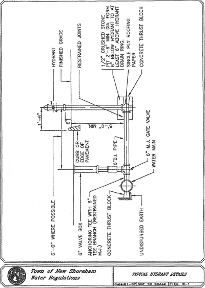
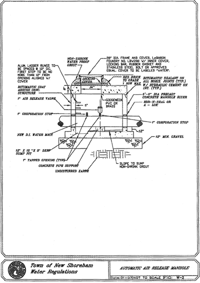
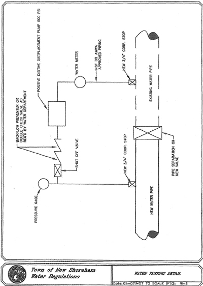
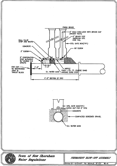
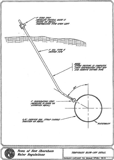
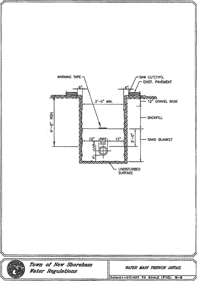
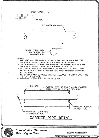
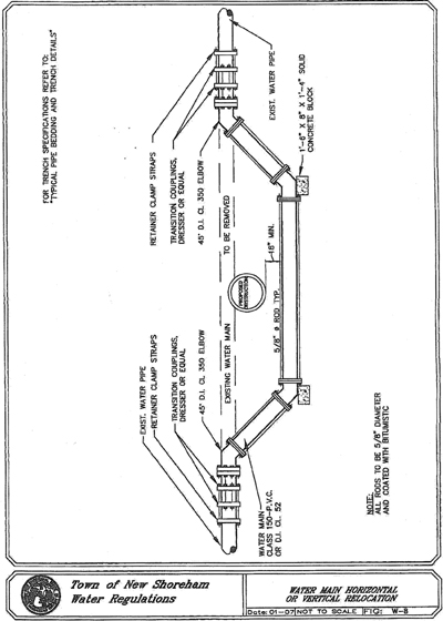

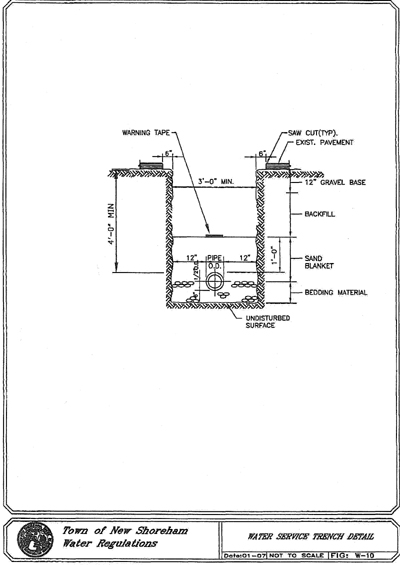
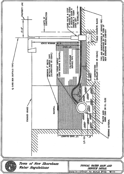
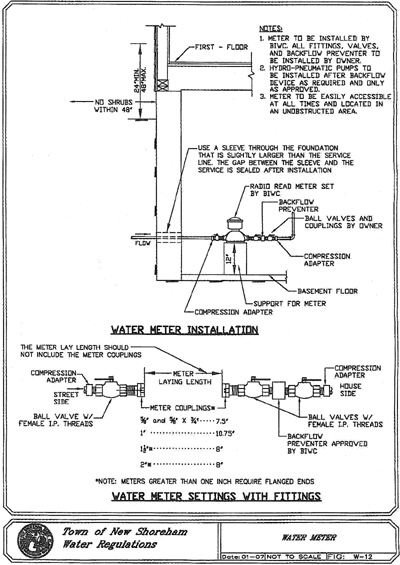
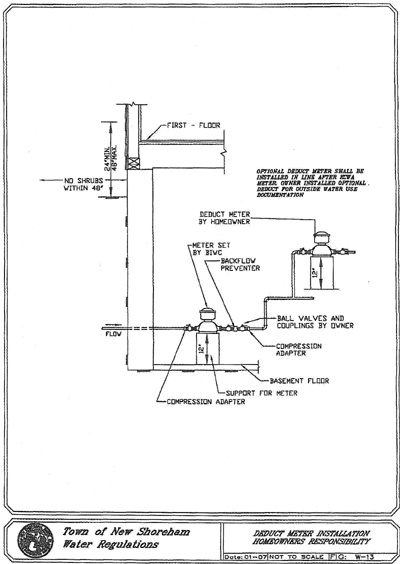
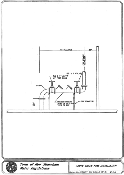
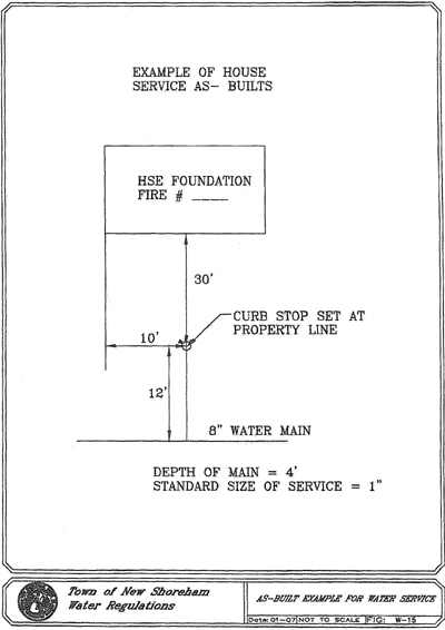
ARTICLE C
Storm Drainage
DIVISION I
STORM DRAINAGE SYSTEM SPECIFICATIONS
§ 1. Part 1 — General.
1.1 Description of Work.
A. The work consists of furnishing and installing a storm drainage system including precast concrete drain manholes, catch basins, and drop inlets with accessories, pipe and fittings, jointing, excavation and backfill, bedding material, and all other related and appurtenant work complete in place and in accordance with the requirements set forth, or as directed.
1.2 Special Requirements.
A. All Approvals and Permits as set forth in the Town of New Shoreham Ordinance, including Approval from the Departments of Environmental Management and Coastal Resources Management, must be obtained prior to construction of a Storm Drainage System.
B. The New Shoreham Public Works Department shall be notified 48 hours in advance to inspect the construction.
1.3 Submittals.
A. General. All submittals shall be submitted to the New Shoreham Director of Public Works, P.O. Drawer 220, Block Island, Rhode Island 02807.
B. Contract Drawings. Submit three sets of drawings of proposed sanitary sewage system for review.
C. Record Drawings. At completion of project, submit record drawings of installed storm drainage piping showing a minimum of three ties from permanent installations such as poles, hydrants, etc., for manholes and catch basins.
§ 2. Part 2 — Products.
2.1 Pipe.
A. Polyvinyl Chloride Pipe (six inches - 15 inches) and Fittings. Polyvinyl chloride (PVC) pipe and fitting shall be in accordance with the latest issue of ASTM D3034, SDR35 and applicable documents. The PVC pipe and fittings shall be composed of clean, virgin class 12364-C compounds conforming to ASTM D1784 and shall be bell and spigot with rubber ring joints. The bell shall consist of an integral wall section with a solid cross section rubber ring securely locked in place to prevent dislocation of the ring. Standard lengths shall be 20 feet and 12.5 feet, plus or minus one inch. Minimum "pipe stiffness": at 5% deflection shall be 46 for all sizes when tested in accordance with ASTM Designation D2412, external loading properties of plastic pipe by parallel-plat loading. All fittings and accessories shall be manufactured and furnished by the pipe supplier and have bell and/or spigot configurations compatible with that of the pipe fittings and shall be of the same strength and quality as the pipe.
B. Polyvinyl Chloride Pipe (greater than 15 inches) and Fittings. Polyvinyl chloride (PVC) pipe and fittings shall be in accordance with the latest issue of ASTM F679. The PVC pipe and fittings shall be composed of clean, virgin, Class 12454C or 13364C compounds and shall be bell and spigot with rubber ring joints. The bell shall consist of integral wall section with a solid cross section rubber ring. Standard lengths shall be 13 feet plus or minus one inch. Minimum "pipe stiffness": at 7 1/2% deflection shall be 46 for all sizes when tested in accordance with ASTM Designation D2412. All fittings and accessories shall be as manufactured and furnished by the pipe supplier and have bell and/or spigot configurations compatible with that of the pipe fittings and shall be of the same strength and quality as the pipe.
C. Ductile Iron Pipe and Fittings. Ductile iron pipe shall be furnished in accordance with ANSI Designation A21.51. The ductile iron pipe shall be thickness Class 52. Pipes shall have normal laying lengths of at least 18 feet. In addition, each length of pipe shall be cement lined and receive a factory applied interior and exterior coating of Kopper's Bitumastic Super Service Black or an approved coating of equal specifications in accordance with ANSI Designation A21.4. Ductile iron pipe shall be push-on type of joint which employs rubber gasket. Joints shall be in accordance with the latest ANSI standard for "Rubber Gasket joints for Ductile Iron Pressure Pipe and Fittings", Designation A21.11. Fittings shall be in accordance with ANSI 23.53 with mechanical joints. The fittings shall be coated inside and outside with a bituminous asphalt paint.
D. Polyethylene Pipe. Polyethylene pipe and fittings shall be manufactured from high density polyethylene resin compound which shall meet the requirements of Type III, Class C, Category 5, Grade P34 per ASTM 1248.
E. Bituminous Coated Corrugated Metal Pipe. Bituminous Coated corrugated pipe shall conform to the requirements of AASHO M-36. Pipe shall be manufactured of galvanized sheet gauge No. 12. Pipe and coupling bands shall be fully coated with bitumastic material as specified for Type C, in accordance with AASHO M-
190. Coupling bands shall be manufactured of galvanized sheet gauge No. 14. Special sections such as fittings, elbows and flared end sections shall be manufactured from galvanized sheet gauge No. 12 to conform to AASHO M-36 and AASHO M-190.
F. Reinforced Concrete Pipe. Reinforced concrete pipe and flared end sections shall conform to the requirements of ASTM C-76, ASTM C-655, and AASHO M-170.
G. Perforated Polyvinyl Chloride Pipe. Perforated polyvinyl chloride (PVC) pipe shall conform to ASTM D-3034, SDR 35. Perforations shall consist of 2 rows of 15 mm holes positioned at 120° radially on the pipe and spaced to provide a minimum total cross-sectional hole area of 1933 mm2 per meter of length. Pipe shall be supplied with friction-fit bell ends.
H. Porous Concrete Pipe. The porous concrete pipe shall conform to the requirements of ASTM C-654 and AASHTO M-176.
2.2 Precast Concrete Drain Manholes and Catch Basins.
A. Precast Concrete Drain Manholes. Manhole bases, risers, eccentric cone and flat- slab-top shall consist of precast reinforced concrete manufactured in accordance with ASTM C-478 and be designed for H20 wheel loading.
The horizontal joints between sections shall be sealed using flexible butyl resin sealant and shall conform to Federal Specifications SS-S-210A and AASHTO M- 198B.
B. Precast Concrete Catch Basins. Base, riser sections, and flat-slab-top shall consist of precast reinforced concrete conforming to ASTM C-478 and be designed for H20 wheel loading. The horizontal joints between sections shall be sealed using a flexible butyl resin sealant and shall conform to Federal Specifications SS-S- 210A and AASHTO M-198B.
C. Pipe Connectors. Resilient complying with ASTM C923. For pipes up to 24 inches, the pipe connectors shall be Kor-N-Seal and for pipe over 24 inches, the pipe connector shall be A-Lok or equal.
D. Manhole Steps. Manhole steps shall be of safety type and shall be cast into the units during process of manufacture. Steps shall be steel reinforced copolymer polypropylene plastic step conforming to ASTM C478 or aluminum forgings alloy 6016, Temper T-16 and those parts which are embedded in the concrete shall be thoroughly cleaned and given a heavy coating of zinc chromate or other approved paint. In addition, steps shall conform to OSHA regulations.
E. Frames, Covers and Grates. Cast-iron manhole frames, covers and grates shall conform to the requirements of AASHTO M105. Castings shall be true to pattern and free from flaws. The bearing surfaces of the frames, cover and grates shall be machined so as to give continuous contact through their circumference and shall be non-rocking. The design on the cover shall be diamond with the word "DRAIN" lettering cast into the top surface.
F. Brick Masonry and Mortar Cement. Brick shall be Grade SM, ASTM C-32 or Grade SM, AASHTO M-91. All brick shall be common hard rubber clay brick and shall be uniform and regular in shape and size. Mortar cement for masonry shall conform to ASTM Designation C-144. The mortar cement shall be composed of one part masonry cement to 2 1/2 parts sand with water not to exceed 4.1 gallons per 70 pound bag of masonry cement. If using Portland cement, lime putty may be added in such amounts that the hydrated lime does not exceed 15% by weight of cement.
2.3 Gravel base.
A. Gravel shall be free of foreign material such as loam, silt, clay and vegetable matter and meet the following requirements:
Passing 1 1/4-inch sieve 100%
| Passing 1/4-inch sieve | 30% - 65% |
| Passing No. 40 | 5% - 50% |
| Passing No. 100 | 0% - 10% |
2.4 Bedding Material.
A. The bedding material shall be crushed stone consisting of durable crushed rock or durable crushed gravel stone, free from ice, snow, sand, clay, loam or other deleterious material. The crushed stone shall conform to the requirements of 100% passing the 3/4 inch screen, 10% to 50% passing the one-half-inch screen, 0% to 20% passing the three-eighths-inch screen and 0% to 5% passing the number four sieve.
2.5 Sand Blanket.
A. The sand shall be free from ice, snow, roots, sod, rubbish, and other deleterious or organic matter. The sand blanket shall conform to the requirements of 100% passing the 1/2 inch screen, 85% - 100% passing the 3/8 inch screen, 60% - 85% passing the number #4 sieve, 35% - 60% passing the number 16 sieve, 10% - 35% passing the number #50 sieve and 2% - 10% passing the number #100 sieve.
2.6 Backfill.
A. Backfill shall be excavated material free-draining clean granular soil suitable for backfill. Up to 20% of backfill material may be rock-like materials not to exceed
0.05 cubic feet in volume, nor more than six inches in length. The backfill shall not contain any debris, pavement, frozen material, organic matter or peat.
2.7 Bedding Material for Rip Rap.
A. The Bedding Material for Rip Rap shall meet the following gradation:
| Passing 2-inch sieve | 100% |
| Passing No. 16 sieve | 50% |
| Passing No. 50 sieve | 0 - 15% |
2.8 Stone Rip Rap.
A. The Stone for Rip Rap shall meet the following class:
| | Size Inches (square openings) | ||
| Modified NSA No. | 100% Passing | 50% Passing | 0 - 15% Passing |
| R-4 | 14 | 7 | 4 |
§ 3. Part 3 — Execution.
3.1 Inspection.
A. The New Shoreham Department of Public Works shall be notified prior to installation of a storm drain system so that inspections can be made throughout the project.
3.2 Product Handling.
A. Each product shall be handled into its position in the trench in such a manner and by such means as the manufacturer recommends as satisfactory, and these operations will be restricted to those considered safe for the workmen and such as to cause no injury to the product or any property.
B. The contractor will be required to furnish slings, straps, and/or other devices to provide satisfactory support of the pipe when it is lifted. Transportation from delivery areas to the trench shall be restricted to operations which can cause no injury to the product. The products shall not be dropped from trucks or into the trench.
C. The contractor shall have on the job site with each crew, all the proper tools to handle the products being installed. The use of hammer and chisel or any other method which results in rough edges, chips and damages, shall be prohibited.
3.3 Excavation and Backfill for Pipes.
A. The width of the trench shall be held to a minimum consistent with the space required to permit satisfactory jointing of the pipe and tamping of the bedding and backfill material under and around the pipe. In general, the maximum trench width shall be the pipe diameter plus two feet or a minimum width of three feet, whichever is greater. If necessary, sheeting and/or shoring shall be used to prevent overcutting at the level of the top of the pipe and to maintain the trench sides. The trench bottom should be smooth, level and all large stones or rocks lying on or protruding from the trench bottom shall be removed.
Over-excavation shall be refilled in six-inch lifts with approved granular material and compacted to 95% maximum density.
B. Where unsuitable material is encountered at the trench bottom, the material shall be excavated to a stable bottom and refilled with compacted bedding material in six-inch lifts.
C. Backfill from the centerline of the pipe to the height two feet above the pipe shall be sand blanket material placed evenly the full width of the trench and compacted. The remainder of the trench shall be backfill material and compacted in twelve-inch layers. Cushion and backfill material shall be compacted to 95% maximum density by tamping and compacting in layers (one-foot maximum) to achieve the required compaction.
3.4 Installation of Pipe.
A. Each pipe length shall be inspected for cracks, defects in coating or lining, and any other evidences of unsuitability. Before lowering in place, the pipe shall be struck with a suitable tool to verify its soundness.
B. Pipe shall be laid in the dry and at no time shall water in the trench be permitted to flow into the pipe.
C. The pipe shall then be laid on the trench bedding as shown in the trench detail, and the spigot pushed home. Jointing shall be in accordance with the manufacturer's instructions and appropriate ASTM standards, and the contractor shall have on hand for each pipe-laying crew, the necessary tools, gauges, pipe cutters, etc. necessary to install the pipe in a workmanlike manner. Pipe laying shall proceed upgrade with spigot ends pointing in the direction of flow.
D. Blocking under the pipe will not be permitted except where a concrete cradle is proposed, in which case precast concrete blocks shall be used.
E. After the pipe has been set to grade, additional bedding material shall be placed in six-inch layers up to the spring line of the pipe. Tamping bars shall be carefully employed to assure compaction of the bedding under the lower quadrants of the pipe for the full width of trench excavation.
F. If a trench box is being used and the trench box is below the spring line of the pipe, the trench box shall be lifted vertically and the stone bedding shall be thoroughly compacted to the trench wall. The trench box shall not be pulled horizontally along the trench.
G. At any time that work is not in progress, the end of the pipe shall be suitability closed to prevent the entry of animals, earth, etc.
H. Unsatisfactory work shall be dug up and re-installed to the satisfaction of the Department of Public Works.
3.5 Installation of Drain Manholes and Catch Basins.
A. Bases for all drain manholes and catch basins shall be placed on a minimum of six inches of compacted bedding material. The excavation shall be properly dewatered and maintained dry while placing bedding material and setting the bases. Manholes shall be backfilled evenly and in layers, maximum one-foot thick, with suitable backfill material and compacted to achieve 95% maximum density.
B. Sheeting and/or bracing shall be used when required.
C. Manhole barrel and cone sections shall be set so as to be vertical and in true alignment.
D. Where required for future connections, openings shall be cast in the manholes at the proper location and shall be sealed with plugs.
E. The inverts of all drain manholes shall be constructed of brick and formed in accordance with the details.
F. Bricks shall be laid in a workmanlike manner, true to line and the joints shall be carefully struck and pointed on the inside. Bricks shall be thoroughly wet when laid and each brick shall be laid in mortar so as to form full bed, end and side joints in one operation. The outside of the brickwork shall be neatly plastered with 1/2-inch layer of cement mortar as the work progresses. The brickwork shall be satisfactorily bonded to the concrete and cast iron frame. No brick masonry shall be laid in water, or any water allowed to rise on the brickwork until the masonry has set for at least 24 hours.
G. All lift holes shall be filled with non-shrinking mortar such as Quick-Plug prior to backfilling.
3.6 Connections to Existing Drain Manholes.
A. Connections to existing drain manholes shall be made so as not to damage the structure. The crown of the new pipe shall be at the same elevation as the main of the largest existing pipe. The openings shall be cored and Kor-N-Seal boot shall be installed. The inverts shall be modified as directed to accommodate flow from the new pipe.
3.7 Cleaning and Flushing of Storm Drain System.
A. Each completed section of pipe shall be cleaned and flushed including drain manholes, catch basins and inlet structures at the end of the project to the satisfaction of the Department of Public Works.
DIVISION II
STORM DRAINAGE REQUIREMENTS DETAILS
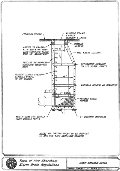
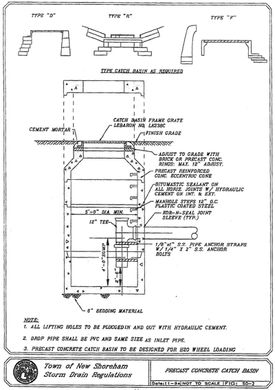
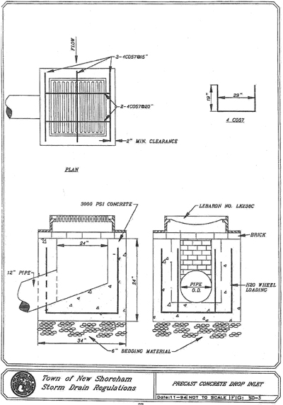
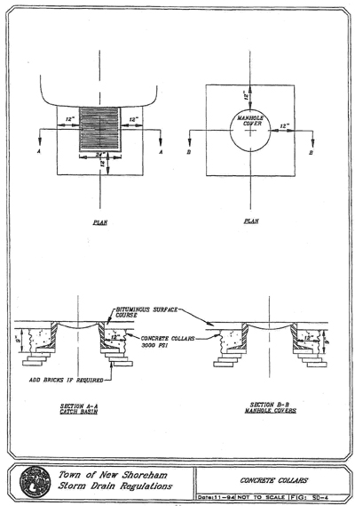
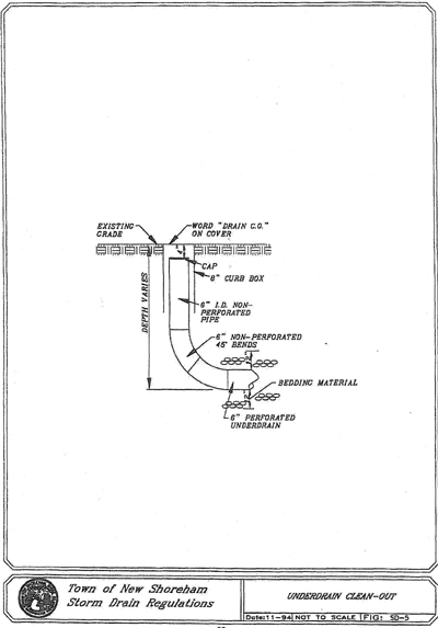
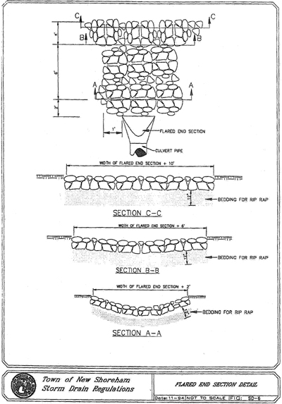
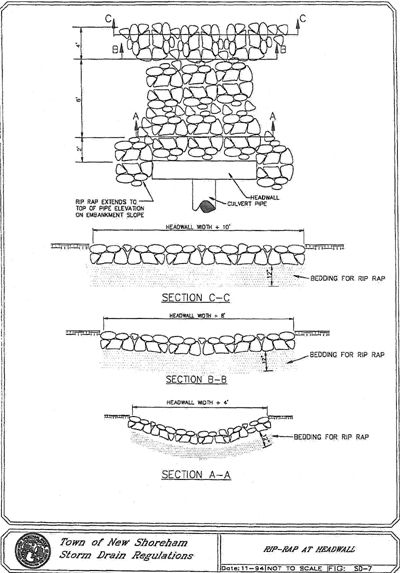
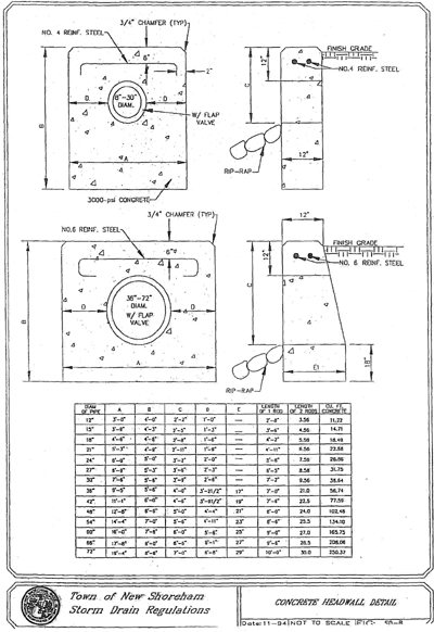
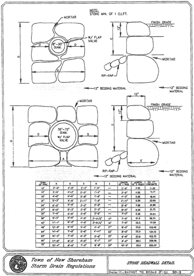
ARTICLE D
Roadway Regulations
DIVISION I
BITUMINOUS PAVING SPECIFICATIONS
§ 1. Part 1 — General.
1.1 Description of Work.
A. Perform all work necessary and required for the construction of temporary pavement and replacement of temporary pavement. Such work includes but is not limited to the following:
1. Gravel base course.
2. Asphalt-aggregate, central-plant, hot-mix, bituminous pavement.
3. Tack coat.
4. Saw cutting and patching existing road.
B. Bituminous paving shall conform to the requirements of the New Shoreham Department of Public Works.
C. The Contractor is responsible for the roadway restoration on Town roadway for a one-year period from the day of acceptance by the Town of New Shoreham.
1.2 Environmental Conditions.
A. Bituminous paving shall not be placed when the ambient temperature is below 40° F., when there is frost in the base, or any other time when weather conditions are unsuitable for the type of materials being placed.
1.3 Protection.
A. After final rolling, no vehicular traffic of any kind shall be permitted on paving until it has cooled and hardened, and in no case less than six hours.
B. Any damaged pavement resulting from work under this contract shall be repaired by the contractor.
§ 2. Part 2 — Products.
2.1 Materials.
A. Gravel Base. Gravel shall be free of foreign material such as loam, silt, clay and vegetable matter and meet the following requirements:
| Passing 1 1/4-inch sieve | 100% |
| Passing 1/4-inch sieve | 30% - 65% |
| Passing No. 40 | 5% - 50% |
Passing No. 100 0% - 10%
B. Backfill. Backfill shall be excavated material free-draining clean granular soil suitable for backfill. Up to 20% of backfill material may be rock-like materials not to exceed 0.05 cubic feet in volume, not more than six-inches in length. The backfill shall not contain any debris, pavement, frozen material, organic matter or peat.
2.2 Bituminous Pavement Materials.
A. Asphalt. The asphalt material shall conform to the requirements of the applicable table in "Specifications for Asphalt Cements and Liquid Asphalts", Specification Series No. 2, The Asphalt Institute. Paving asphalt shall be steam-refined paving asphalt with penetration grades of 85-100 for roads and 60-70 for parking areas. The amount of asphalt to be mixed with the mineral aggregate shall be between 3% - 6% by weight for binder course and between 6.5-8% by weight for wearing course. The exact amount of asphalt to be mixed with the mineral aggregate shall be such that a hard, unyielding paving will be the result.
B. Mineral Aggregate. Coarse and fine mineral aggregate shall consist of broken stone, crushed gravel, natural materials having sufficient roughness when combined within the specified limits for grading, or a mixture thereof. If gravel is used, not less than 15% nor more than 30% limestone screenings by weight shall be added to the gravel as a separate ingredient so as to meet the gradation limits. If crushed stone is used, not less than 15% nor more than 30% sand by weight shall be added to the crushed stone as a separate ingredient to meet the gradation limits. The material shall be tough, durable, and sound, and shall be free from organic matter and other deleterious substances, and shall conform to the following gradation:
| a. | Wearing Course. Passing 3/4-inch | 100% |
| | Passing 1/2-inch | 80% - 100% |
| | Passing 3/8-inch | 70% - 90% |
| | Passing No. 4 sieve | 50% - 70% |
| | Passing No. 8 sieve | 35% - 50% |
| | Passing No. 30 sieve | 18% - 29% |
| | Passing No. 50 sieve | 13% - 23% |
| | Passing No. 100 sieve | 8% - 16% |
| | Passing No. 200 sieve | 3% - 8% |
| b. | Binder Course. | |
| | Passing 1 1/4-inch | 100% |
| | Passing 3/4-inch | 60% - 80% |
| | Passing 3/8-inch | 35% - 60% |
| | Passing No. 8 sieve | 20% - 35% |
Passing No. 50 sieve 3% - 12%
Passing No. 200 sieve 0% - 4%
2.3 Mixing.
A. Surface course shall be mixed at a central mixing plant by either batch mixing or continuous mixing, at a temperature not exceeding 325° F. The completed mixture, tested at any time or at any location, shall have a uniform distribution of asphalt binder, as determined by the extraction test, as performed in accordance with ASTM test method D2172.82. The bitumen ratio (pounds of asphalt per 100 pounds of dry aggregate), computed from laboratory extraction analysis, shall not vary more than 5% above or 10% below the exact amount predetermined to obtain hard unyielding paving.
2.4 Tack coat.
A. A tack coat of asphalt emulsion SS-1 (diluted to 50%) not to exceed 0.10 gallons per square yard, shall be sprayed by a distribution truck capable of spraying the emulsion uniformly over the underlying course.
§ 3. Part 3 — Execution.
3.1 Weather Limitations.
A. Bituminous Concrete pavement shall not be placed on a wet or damp surface or when the temperature of the surface is less than 40° F., measured prior to placement. Air temperature shall be 40° F. and rising.
3.2 Remove and Dispose of Existing Pavement.
A. Existing bituminous pavement shall be removed and disposed of properly. All edges shall be sawcut to a straight smooth line.
3.3 Pavement.
A. As soon as the backfill has been compacted to 95% density, the two inches temporary pavement shall be placed. The temporary pavement shall remain for a period no less than 90 days at which time the contractor shall remove the temporary pavement and re-sawcut the trench 12-inches beyond the temporary pavement edges and install the permanent pavement. The contractor will be responsible for the temporary pavement during the ninety-day period.
3.4 Gravel Base Course.
A. Gravel base shall be of thickness indicated on detail.
3.5 Surface Preparation.
A. Immediately before applying binder course, the area to be surfaced shall be cleaned of all loose material. Binder course shall not be applied until base course preparation has been completed, and only so far in advance of placing the surfacing as may be permitted by the New Shoreham Department of Public Works.
3.6 Bituminous Pavement.
A. Surface Preparation. In advance of placing asphalt concrete and before placing adjacent to cold transverse construction joints, such joints shall be trimmed to a vertical face and to a neat line and tack coat shall be applied to all edges.
B. Spreading. The spreading and finishing equipment shall be of the self-powered type and shall have a floating screen assembly controlled as to elevation strike off. The use of any spreading and finishing equipment which causes blemishes or conditions of non-uniformity which are not satisfactorily corrected by the scheduled operations shall be discontinued and other satisfactory spreading and finishing equipment shall be provided by the contractor.
C. Compacting Surface Course.
1. While hot and as soon as it will bear the roller without displacement of hair cracking, the surface course shall be uniformly compressed by a power driven tandem roller, mechanically wetted, weighing not less than 350 pounds per linear inch width of tread and the roller shall weigh not less than 10 tons. Rolling shall start longitudinally at the sides and process toward the center of the pavement, overlapping on successive trips by at least one-half of the width of the rear wheels of the roller. Rolling shall continue until all roller marks are eliminated, the surface is of uniform texture and true to grade and cross-section, and a density of at least 96% of the laboratory density specified in ASTM D-1559 is obtained.
2. The roller shall be operated by a competent, experienced roller operator and shall be kept in as nearly continuous operation as practical while the work is underway.
D. Special Instructions. In addition to the requirements of this specification, roadway paving shall conform to all state and local regulations and specifications.
E. State Roads. On state roads, the contractor shall obtain the required Utility Permit from RIDOT and the work shall be in accordance with the Permit.
DIVISION II
CEMENT CONCRETE WALKS SPECIFICATIONS
§ 1. Part 1 — General.
1.1 Related Documents.
1.2 Description of Work.
A. Perform all work necessary and required for the replacing of new or existing concrete walks. Such work includes but is not limited to the following:
1. Subgrade preparation.
2. Gravel base course.
3. Formwork.
4. Concrete mixing, placing, finishing, and curing.
5. Control and isolation joints.
6. Precast curb.
7.
8. Cement concrete walks shall conform to the New Shoreham Department of Public Works requirements.
1.3 The Contractor will be responsible for the restored or new concrete sidewalk for a period of one year from the date of acceptance by the Department of Public Works. The Contractor shall repair damaged concrete and clean concrete discolored during this period. Sidewalk that is damaged shall be removed and reconstructed for the entire length between regularly scheduled joints. Refinishing the damaged portion will not be acceptable.
§ 2. Part 2 — Products.
2.1 Materials.
A. Concrete.
1. Concrete shall have a minimum compressive strength of 3,000 lbs. per square inch at 28 days. The maximum size of coarse aggregate shall be 1 1/ 2 inches. Concrete shall have a slump of not more than three inches. The concrete mixtures shall have air content by volume of concrete, based on measurements made immediately after discharge from the mixer, 5% to 7% air content shall be determined in accordance with ASTM C 173.
B. Gravel Base.
1. Subgrade shall consist of gravel meeting the following requirements:
a. Passing 1 1/4-inch sieve: 100%.
b. Passing 1/4-inch sieve: 30% - 65%.
c. Passing No. 40 sieve: 5% - 30%.
d. Passing No. 100 sieve: 0% - 10%.
C. Backfill. Backfill shall be excavated material free-draining clean granular soil suitable for backfill. Up to 20% of backfill material may be rock-like materials not to exceed 0.05 cubic feet in volume, nor more than six-inches in length. The backfill shall not contain any debris, pavement, frozen material, organic matter or peat.
§ 3. Part 3 — Execution.
3.1 Subgrade Materials.
A. The subgrade shall be constructed true to grade and cross section. The subgrade shall be thoroughly wetted and then compacted with two passes of 500 lb. roller. Yielding material deflecting more than 1/2-inch under the specified roller shall be removed to a depth equal to the thickness of pavement indicated on plans and replaced with an approved granular material which shall be tested for grade and cross section with a template extending the full width of the sidewalk and supported between side forms.
3.2 Gravel Base.
A. Gravel base shall be of thickness indicated on detail.
3.3 Forms.
A. Forms shall be of wood or steel, straight, of sufficient strength to resist during depositing and consolidating concrete, and of height equal to the full depth of the finished sidewalk. Wood forms shall be surfaced planned, two inches nominal thickness. Steel forms shall be of approved section with a flat top surface. Forms shall be set with the upper edge true to line and grade and shall be held rigidly in place by stakes placed at intervals not to exceed four feet. Forms shall be coated with form oil each time before concrete is placed. Wood forms may, instead, be thoroughly wet with water before concrete is placed, except that with probable freezing temperatures, oiling is mandatory. Side forms shall not be removed for less than 12 hours after finishing has been completed.
3.4 Concrete Placement and Finishing.
A. The surface shall be finished with a wooden float and followed by broom finish. No plastering of the surface will be permitted. All outside edges of the slab and all joints shall be edged with a 1/4-inch radius edging tool.
3.5 Control Joints.
A. The control joints shall be formed in the fresh concrete by cutting a groove in the top portion of the slab to a depth of at least one-fifth of the sidewalk slab thickness using a jointer to cut the groove. Control joints shall occur at same dimension and not greater than four feet intervals.
B. Unless otherwise specified, control joints shall occur at the same dimension as the width of walk.
3.6 Isolation Joints.
A. Unless otherwise specified, isolation joints shall occur at the following locations.
1. Between walk and curb.
2. Intersections of walk.
3. Between walk and building walls.
4. Between walk and all structure, i.e., walls and planters.
5. On continuous walks, isolation joints shall be a minimum of 40 feet apart.
B. Isolation joints shall occur between wall and curb, intersection of walk and on continuous walks every 40 feet apart. Isolation joints shall be filled with 1/2-inch thick joint filler strips conforming to ASTM D 1751. Joint filler shall be placed with top edge one-half-inch below the surface and shall be held in place with steel pins or other devices to prevent warping of the filler during floating and finishing. Immediately after finishing operations are completed, joint edges shall be rounded with the edging tool having a radius of 1/4-inch, and concrete over the joint filler shall be removed. Isolation joints shall be formed about structures and features that project through or into sidewalk pavement, using joint filler of the type, thickness and width indicated. The filler shall be installed in such a manner as to form a complete, uniform separation between the structure and sidewalk pavement. At the end of the curing period, expansion joints shall be carefully cleaned and filled with joint sealer conforming to ASTM D 1850. The concrete at the joint shall be surface dry, and the atmospheric and pavement temperatures shall be above 50° F. at the time of application of joint sealing materials. The joints shall be filled flush with the concrete surface in such a manner as to minimize spilling on the walk surface. Spilled sealing material shall be removed immediately and the surface of the walk cleaned.
C. Unless otherwise specified, decorative line scoring shall occur every four linear feet.
3.7 Surface Uniformity.
A. The completed surface shall be uniform in color and free of surface blemishes and tool marks.
3.8 Curing.
A. Immediately after the finishing operations, the exposed concrete surface shall be cured by preventing the loss of moisture for seven days by the mat, impervious- sheet or membrane-curing method.
3.9 Backfilling.
A. After curing, debris shall be removed, and the area adjoining the sidewalk shall be backfilled, graded and compacted to conform to the surrounding area in accordance with the lines and grades indicated.
DIVISION III
GRAVEL ROAD MIX SPECIFICATIONS
§ 1. Part 1 — General.
1.1 Description of Work.
A. Perform all work necessary and required for the construction of gravel road mix. Such work includes but is not limited to the following:
1. Gravel base.
2. Gravel road mix of three parts gravel base, one part blue stone dust and one part crushed stone.
B. The Contractor is responsible for the roadway restoration on Town roadway for a one-year period from the day of acceptance by the Town of New Shoreham.
§ 2. Part 2 — Products.
2.1 Materials.
A. Gravel Borrow: The gravel borrow shall be of a granular nature, the major portion of which may be sand and gravel. It shall be free from peat, vegetable or organic matter and any other debris. Common borrow shall conform to the following requirements.
| | Passing 4-inch sieve Passing No. 4 sieve Passing No. 40 sieve Passing No. 200 sieve | |
| B. | Gravel Base: Sub-grade requirements: shall consist Of gravel meeting the following | |
| | Passing 1 1/4 inch sieve | |
| | Passing 1/4 inch sieve | |
| | Passing No. 40 sieve | |
| | Passing No. 100 sieve | |
100%
45% - 75%
10% - 35%
0% - 8%
100%
30% - 65%
5% - 30%
0% - 10%
C. Blue Stone: The blue stone dust shall consist of the fine particles of crushed rock by-product resulting from crushing operations.
D. Crushed Stone: Crushed stone shall meet the requirement that 100% by weight shall pass the 3/4-inch sieve and shall be free from loam, clay, vegetable matter and soft elongated pieces of rock.
E. Backfill: Backfill shall be excavated material free-draining clean granular soil suitable for backfill. Up to 20% of backfill material may be rock-like materials not to exceed 0.05 cubic feet in volume, nor more than six inches in length. The backfill shall not contain any debris, pavement, frozen material, organic matter or peat.
§ 3. Part 3 — Execution.
3.1 Weather Limitations.
A. Gravel road mix shall not be placed during rain or on frozen surfaces.
3.2 Remove and Dispose of Existing Pavement.
A. Existing road surfaces shall be removed and disposed of properly. All edges shall be sawcut to a straight smooth line.
3.3 Gravel Road Mix Placement.
A. The gravel road mix shall be placed on a prepared gravel base and compacted not less than 95% of the maximum density determined in accordance with AASHTO T99, Method A or D.
B. Special Instructions. In addition to the requirements of this specification, roadway paving shall conform to all state and local regulations and specifications.
3.4 Gravel Base.
A. Gravel base shall be of thickness indicated on detail.
DIVISION IV
EROSION AND SEDIMENT CONTROL SPECIFICATIONS
§ 1. Part 1 — General.
1.1 Description of Work.
A. Furnish and install temporary control measures as needed during the progress of the work or as ordered by the Director of Public Works during the life of the project to control water pollution through use of silt fences, baled hay checks and other erosion control devices and methods.
B. The Contractor is responsible for compliance with the rules and regulations governing the enforcement of the Rhode Island Freshwater Wetlands Act and the Coastal Resource Management Council.
C. Erosion and sediment control shall be in accordance with "The Rhode Island Erosion and Sediment Control Handbook", prepared by the U.S. Department of Agriculture, Soil Conservation Service (latest revision).
§ 2. Part 2 — Products.
2.1 Materials.
A. Silt Fence. Silt fence shall be propex silt stop manufactured by Mirafi 140N, Trevira 1127 or equal.
B. Hay Bales. Hay bales shall be mowings of acceptable herbaceous growth reasonably free from noxious weeds or woody stems and shall be reasonably dry. Hay bales shall be approximately 36 inches long x 28 inches wide x 24 inches high. Bales shall be anchored with two inches x two inches x three feet long wooden stakes.
§ 3. Part 3 — Execution.
3.1 Preparation.
A. Contractor shall have on-site all necessary hay bales, silt fence installed, prior to undertaking any work that may cause erosion.
B. In the event of conflict between these requirements and pollution control laws, rules and regulations of the Federal, State or local agencies, the more restrictive laws, rules or regulations shall apply.
3.2 Installation Location of Baled Hay and Silt Fences.
A. During construction, baled hay shall be placed and maintained around all catch basins, unless indicated otherwise. Silt fence along with hay bales shall be installed prior to undertaking any operations. Silt and debris shall be removed from catch basins and drainage piping and base of silt fences at end of construction.
3.3 Trench Dewatering.
A. The discharge of trench dewatering to catch basins or surface waters shall be made through sedimentation basins constructed from hay bales. The Contractor will also be required to remove accumulated sediment from the basins periodically and at the end of the project the sedimentation basins shall be removed.
3.4 Special Instructions.
A. It is the Contractor's responsibility to maintain the placement of hay bales and silt fences, remove silt from ditches and culverts and to repair any erosion of ditches and slopes.
B. Any erosion, siltation or general damage resulting from neglect by the Contractor to undertake erosion control measures as required or directed shall result in the responsibility of the Contractor to correct.
C. (Reserved)
D. The erosion control features installed by the Contractor shall be acceptably maintained by the Contractor throughout the project.
E. Any wetland contaminated by the sediment from this project must be restored to its original condition. If this procedure is not sufficient to restore plant growth, direct seeding as determined by the State's biologist or the Director of Public Works will be required at the beginning of the spring growing season. Removal of sediment and any required reseeding or planting shall be done by the Contractor.
F. After completion of all construction, the construction through the wetland, corridor, or adjacent to, shall be seeded with a mixture of Canary Grass and Red Top.
G. At the completion of the Project, the Contractor shall remove the silt fences and wooden stakes. The hay bales may be left in place unless directed by the Director of Public Works.
DIVISION V
ROADWAY REQUIREMENTS DETAILS